This tutorial is part of: WiFi LoRa 32 Tutorials
All videos related to Heltec WiFi LoRa 32 are related using this group. Links to other videos are below this article.
DIY Remote Relay Project: 13 Mile No-Wi-Fi/No-SIM Heltec LoRa 32 Module
Long-Range LoRa Remote Control with Heltec WiFi LoRa 32
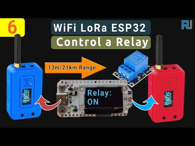
Imagine being able to control a fan, a light, a water pump, or a security alarm from over 15 miles or 21 kilometers away, all without needing a SIM card or paying any fees. This is possible using LoRa (Long Range) technology, and in this guide, we'll show you exactly how to build such a system. We will be using the powerful Heltec WiFi LoRa 32 module, conveniently housed inside the rugged Meshnology N35 case which includes a 3000mAh battery for long-lasting operation.
This project will demonstrate how to set up a transmitter and a receiver to control a load in two different ways: a simple on/off function and a toggle function. We'll cover the hardware assembly, wiring, code settings, and show you a real-world range test.
Components and Hardware
At the heart of our project are a few key components designed to work together for maximum range and reliability.
- Heltec WiFi LoRa 32 V3: This is a versatile microcontroller that comes with a built-in LoRa communication chip, as well as Wi-Fi and Bluetooth capabilities. It's fully programmable like an Arduino, allowing us to read inputs and control outputs.
- Meshnology N35 Case & Battery: This is a durable case designed specifically for the Heltec module. When purchased as a kit, it includes a 3000mAh battery, which is essential for long-term transmission and reception, especially in remote locations.
- High-Gain Antenna: To achieve the best possible range, we will use a high-gain antenna, which significantly improves signal strength compared to the stock antenna.
- Relay or Buzzer: For the receiver, you can connect a relay to control high-power AC or DC devices like fans and lights, or a simple buzzer for alarm applications.
Hardware Assembly
Assembling the unit is a straightforward process, as shown in the video starting around 05:56. The N35 kit comes with the Heltec module, the 3000mAh battery, the case, an antenna with an extension cable, and pin headers.
The main steps involve placing the buttons into the case, passing the battery wire through, connecting the antenna extension cable to the module, placing the module inside, and connecting the battery. Then, you simply close the case and secure the antenna mount on the outside. It's worth noting that an early version of the case required a small modification to fit the antenna mount, but Meshnology has since fixed this issue in newer batches.
Wiring for the Receiver's Load
On the receiver side, you'll connect your output device. Below are the wiring instructions for both a relay and a buzzer, as detailed in the video at 11:17.
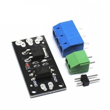
Wiring a Relay
A relay acts as an electrically operated switch, allowing you to control a high-power load.
- The relay's signal pin connects to pin 4 of the Heltec LoRa module.
- The relay's ground pin connects to a GND pin on the module.
- Important: The relay's VCC (power) pin should be powered by an external 5V power supply. The module's 3.3V output cannot reliably handle the relay's current draw.
- You must create a common ground by connecting the ground of the external power supply to the ground of the Heltec module. This is critical for the circuit to work.

Wiring a Buzzer with a Transistor
For a simple audio alarm, you can use a buzzer. To prevent drawing too much current from the microcontroller pin, we use a 2N2222 NPN transistor to drive it.
- Connect pin 4 of the module to a 1kΩ resistor. The other end of the resistor connects to the base (middle pin) of the transistor.
- The transistor's emitter (left pin, with the flat side facing you) connects to GND.
- The transistor's collector (right pin) connects to the negative (-) terminal of the buzzer.
- The positive (+) terminal of the buzzer connects to the 3.3V pin on the Heltec module.

Arduino IDE and Library Setup
Before you can upload the code, you need to configure the Arduino IDE to work with the Heltec boards. The process starts at 14:37 in the video.
- Install ESP32 Boards: In the Arduino IDE, go to the Boards Manager and search for
ESP32. Install the package by Espressif Systems. - Add Heltec Board URL: Go to File > Preferences. In "Additional Boards Manager URLs," add the JSON link for the Heltec ESP32 series. This link will be provided on the resources page below the article.
- Install Heltec ESP32 Boards: Return to the Boards Manager, search for
Heltec ESP32, and install the package. - Install Required Libraries: Go to the Library Manager and install the following:
Heltec ESP32 dev boardsAdafruit GFX Library(and click "Install All" for its dependencies)
- Install Robojax Library: Download the custom
Robojax Heltec LoRa 32zip library from the resources page. In the Arduino IDE, go to Sketch > Include Library > Add .ZIP Library and select the file you downloaded. - Select the Board: Finally, go to Tools > Board and select the Heltec WiFi LoRa 32 (V3).
Code Settings Explained
We have three different code sketches for this project: one for the simple on/off transmitter, one for the toggle transmitter, and one for the receiver. The library handles the complex parts, so you only need to adjust a few settings at the top of each file. The code explanation begins at 19:00 in the video.
Transmitter (TX) - Simple On/Off Code Settings
This code turns the relay on only while the button is held down.
// Text to display on the OLED screen
const char *displayTexttitle = "Relay:";
const char *displayTextTX = "(TX)";
const char *displayTextRelayON = "ON";
const char *displayTextRelayOFF = "OFF";

// Security key and frequency (MUST MATCH RECEIVER)
const char *userKey = "6tfDs$wEq3!";
#define RF_FREQUENCY 915555000

// Transmission power (2-21, higher is stronger)
#define TX_OUTPUT_POWER 14
Transmitter (TX) - Toggle Code Settings
This code toggles the relay's state (on to off, or off to on) with each button press.
// Set to true for serial monitor debugging, false for normal use
bool debug = true;
// The built-in user button pin is 0
#define PUSH_BUTTON_PIN 0

// Text to display on the OLED screen
const char *displayTextTitle = "Relay:";
const char *displayTextTX = "(TX)";
const char *displayTextRelayToggleON = "TOG-ON";
const char *displayTextRelayToggleOFF = "TOG-OFF";

// Security key and frequency (MUST MATCH RECEIVER)
const char *userKey = "6tfDs$wEq3!";
#define RF_FREQUENCY 915555000

// Transmission power (2-21)
#define TX_OUTPUT_POWER 2
Receiver (RX) Code Settings
This single receiver code works with both the simple and toggle transmitters.
// The pin connected to the relay's signal input
#define RELAY_CONTROL_PIN 4

// Text to display on the OLED screen
const char *displayTextTitle = "Relay:";
const char *displayTextTX = "(RX)";
const char *displayTextRelayON = "ON";
const char *displayTextRelayOFF = "OFF";
const char *displayTextRelayToggleON = "TOG-ON";
const char *displayTextRelayToggleOFF = "TOG-OFF";

// Security key and frequency (MUST MATCH TRANSMITTER)
const char *userKey = "6tfDs$wEq3!";
#define RF_FREQUENCY 915555000
Crucially, the userKey and RF_FREQUENCY must be identical on both the transmitter and receiver for them to communicate.
Demonstration and 13-Mile Range Test
The system works flawlessly in a lab environment, with the receiver's relay or buzzer responding instantly to button presses on the transmitter. But the true power of LoRa is its range.
A long-range test was performed, as seen from 25:03 onwards. The transmitter was set to a power level of 20, equipped with a high-gain antenna, and placed on a tripod about 10 meters above the water level on the shore of a lake to ensure a clear line of sight. The receiver was then taken to the other side of the lake.
The result was a stunning success. A stable signal was received from a distance of 13.04 miles, or 20.98 kilometers. This demonstrates that with the right setup, you can reliably control devices over vast distances, making it perfect for applications like remote agriculture monitoring, gate control, or a long-range burglar alarm system.
Video Timestamps
- 00:00 - Introduction to Long-Range Control
- 02:42 - What is LoRa?
- 03:20 - Components Overview (Heltec, N35 Case)
- 05:56 - Unboxing and Hardware Assembly
- 11:17 - Wiring Explained: Relay and Buzzer
- 14:37 - Arduino IDE & Library Setup
- 19:00 - Code Settings Explained (TX and RX)
- 25:03 - Demonstration & 13-Mile Range Test
This tutorial is part of: WiFi LoRa 32 Tutorials
- Using Heltec WiFi LoRa 32 V3 to transmit temperature using DHT22 to 1.4km
- 13 Miles 20km with NO WiFi? How LoRa Sent Voltage Across Crazy Distances! (Heltec WiFi LoRa 32 V3)
- Turn On a Device from 13 mile 21km Away – The Ultimate Off-Grid LoRa Project with WiFi LoRa 32!
- Remote Door Alert System from 13 mile 21 km Away With LoRa – Off the Grid! (Heltec WiFi LoRa 32 V3)
- Control a Servo motor from Miles Away! Heltec WiFi LoRa 32 V3 Arduino Tutorial (TX)
- How to Use the Heltec LoRa CubeCell Development Board HTCC-AB01
Common Course Links
Common Course Files
Resources & references
-
ExternalPurchase Wi-Fi LoRa 32 from Meshnologymeshnology.com
Files📁
Other files
-
Robojax Heltec WiFi LoRa 32 Library Version 1.1.0 20250703
Robojax_HeltecLoRa32_1.1.0_20250702.zip0.09 MB