This tutorial is part of: WiFi LoRa 32 Tutorials
All videos related to Heltec WiFi LoRa 32 are related using this group. Links to other videos are below this article.
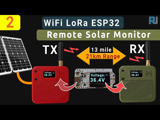
13 Miles 20km with NO WiFi? How LoRa Sent Voltage Across Crazy Distances! (Heltec WiFi LoRa 32 V3)
Build a 13-Mile Off-Grid Voltage Monitor with LoRa and ESP32
Have you ever needed to monitor a remote power source, like a solar panel at a cabin, a battery bank on a boat, or equipment on a large farm, from miles away? This project guide will walk you through building a long-range, off-grid voltage monitor that can transmit data up to an incredible 13 miles (or 21 kilometers), with no subscription fees or reliance on Wi-Fi or cellular networks.
We will use two Heltec WiFi LoRa 32 modules, each housed in a rugged Meshnology N32 case with a 3000mAh battery, to create a transmitter and a receiver. The transmitter will measure a target voltage (from a few volts up to 100V or more) using a simple voltage divider circuit and send the reading wirelessly using LoRa. The receiver will then display this voltage in real-time, allowing you to monitor your systems from miles away.
How It Works: The Voltage Divider
The core of this project is the ability to measure a wide range of voltages. Since the ESP32's input pins can only safely measure voltages up to 3.3V, we cannot connect a 12V or 100V source directly. To solve this, we use a simple circuit called a voltage divider, which steps down the voltage to a safe level for the microcontroller to read. This is explained in the video at 12:26.
The circuit uses two resistors (R1 and R2) connected in series. The high voltage source (Vin) is applied across both resistors, and the ESP32 reads the lower, proportional voltage (Vout) across only the R2 resistor. With the right resistor values, you can accurately measure very high voltages.

When choosing your resistors, a good rule of thumb is to select values that keep the output voltage well below the 3.3V limit, even when measuring the maximum voltage you expect. For the best accuracy, you should measure the actual resistance of your resistors with a multimeter and use those precise values in the code.

Hardware Assembly and Wiring
The assembly involves placing the Heltec LoRa 32 module and the 3000mAh battery inside the N32 case. The case has cutouts for the screen and buttons, and a hole for the external antenna mount. One of the most important safety notes is to always have the antenna connected before powering on the device, as transmitting without an antenna can damage the LoRa module.


Arduino IDE & Library Setup
https://resource.heltec.cn/download/package_heltec_esp32_index.json
To program the Heltec modules, you must first configure your Arduino IDE. This one-time setup is crucial and is detailed at 20:41 in the video.
- Install ESP32 Boards: Add the official Espressif ESP32 boards URL in File > Preferences and install the "esp32" package from the Boards Manager.
- Install Heltec Support: Add the Heltec-specific JSON URL to your preferences. Then, in the Boards Manager, search for and install the "Heltec ESP32" package.
- Install Required Libraries: Using the Library Manager (Sketch > Include Library > Manage Libraries), install the following:
Heltec ESP32 dev boardsAdafruit GFX Library(and its dependencies)
- Install Robojax Library: You will need to download the custom
Robojax_HeltecLoRa32library, which is provided as a .zip file. Install it in the IDE via Sketch > Include Library > Add .ZIP Library. - Select the Board: Finally, go to Tools > Board and select the Heltec WiFi LoRa 32 (V3) and the correct COM port.
Code Configuration Explained
The project uses two separate sketches: one for the Transmitter (TX) and one for the Receiver (RX). You only need to configure a few key settings in the transmitter code for it to work, as explained at 25:02. The receiver code requires matching LoRa settings.
#define VOLTAGE_READING_PIN 4  // The pin reading the voltage
const int R1 = 39120; // Your measured value for R1 in ohms
const int R2 = 3312; // Your measured value for R2 in ohms

const float CALIB_FACTOR = 1.007f; // Calibration factor to match a multimeter

const char *displayTexttitle = "Voltage:"; // Text for the OLED
const char *displayTexTX = "(TX)";

// This security key MUST be IDENTICAL on the TX and RX devices
const char *userKey = "YOUR_SECRE8888";

// These LoRa settings MUST be IDENTICAL on the TX and RX devices
#define RF_FREQUENCY      915000000 // LoRa Frequency in Hz
#define TX_OUTPUT_POWER   2         // TX Power in dBm (2-21)
VOLTAGE_READING_PIN: The GPIO pin on the ESP32 that you've connected to your voltage divider output.R1andR2: Enter the exact resistance values of your two resistors as measured by a multimeter. This is crucial for accuracy.CALIB_FACTOR: If your displayed voltage is slightly off from a trusted multimeter, you can adjust this value up or down (e.g., 1.008 or 0.995) to fine-tune the reading. Set it to1.0to disable.userKey: This is your private security key. Only devices with the exact same key can communicate.RF_FREQUENCY: The operating frequency for LoRa. This must match on both devices and be legal for your region (e.g., 915MHz for North America).TX_OUTPUT_POWER: The transmission power, from 2 (low power, short-range) to 21 (high power, long-range). Higher power uses more battery. For the 13-mile test, a value of 20 was used. For testing on your desk, 2 is sufficient.
The Receiver code has similar settings for userKey and RF_FREQUENCY that must match the Transmitter's settings.
Live Project in Action
Once the code is uploaded, the transmitter unit will begin measuring the voltage from your connected source, displaying it on its own OLED screen with a "(TX)" indicator, and broadcasting the data via LoRa. The receiver unit, when programmed with the matching security key and frequency, will listen for the signal. As soon as it receives a valid transmission, it will display the identical voltage on its screen with an "(RX)" indicator.
As demonstrated in the long-range test at 31:39, this setup is incredibly effective. With high-gain antennas and a clear line of sight, the system successfully transmitted and received accurate voltage readings from 13 miles away, proving it is a robust and reliable solution for serious remote monitoring tasks.
Video Chapters
- 00:00 - Start
- 03:33 - Introduction to the board and LoRa
- 05:47 - N32 Case for WiFi LoRa 32
- 12:26 - Voltage divider to measure up to 150V
- 19:47 - Preparing wire to measure voltage
- 20:41 - Installing library for WiFi LoRa 32
- 25:02 - Transmission Code explained
- 27:16 - Receiver Code explained
- 28:36 - Demonstration of reading voltage
- 31:39 - Real world distance range test (13 mile)
This tutorial is part of: WiFi LoRa 32 Tutorials
- Using Heltec WiFi LoRa 32 V3 to transmit temperature using DHT22 to 1.4km
- Turn On a Device from 13 mile 21km Away – The Ultimate Off-Grid LoRa Project with WiFi LoRa 32!
- Remote Door Alert System from 13 mile 21 km Away With LoRa – Off the Grid! (Heltec WiFi LoRa 32 V3)
- Control a Servo motor from Miles Away! Heltec WiFi LoRa 32 V3 Arduino Tutorial (TX)
- DIY Remote Relay Project: 13 Mile No-Wi-Fi/No-SIM Heltec LoRa 32 Module
- How to Use the Heltec LoRa CubeCell Development Board HTCC-AB01
Common Course Links
Common Course Files
Resources & references
-
External
-
External
-
External
-
External
-
ExternalPurchase Wi-Fi LoRa 32 from Meshnologymeshnology.com
Files📁
Other files
-
Robojax Heltec LoRa 32 V3 Library 1.0 - 2025-05-20This is library for Heltec WiFi LoRa 32 V3. It contains the example codes for projects. Please watch video for instructions on how to install it.
Robojax_HeltecLoRa32_1.0-20250520.zip0.09 MB -
Heltec WiFi LoRa 32 V3 Schematic Diagram (V3.1)
Heltec_WiFiLoRAV3_Schematic_Diagram.pdf0.18 MB