This tutorial is part of: WiFi LoRa 32 Tutorials
All videos related to Heltec WiFi LoRa 32 are related using this group. Links to other videos are below this article.
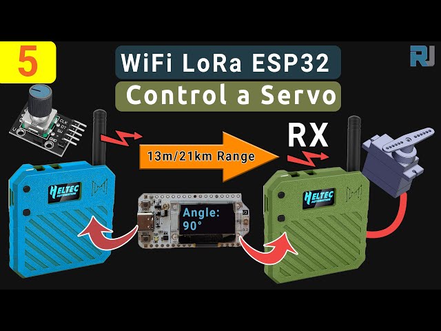
Control a Servo motor from Miles Away! Heltec WiFi LoRa 32 V3 Arduino Tutorial (TX)
In this guide, we are taking the exact sketches from our Heltec ESP32 LoRa V3 servo project and walking through how they work—no extra code added. You’ll learn how the transmitter reads a rotary encoder, secures and sends that angle over LoRa, and how the receiver decrypts it and drives a micro-servo. All part and code links are below, and if you order through our affiliate links it helps us keep making these tutorials.
Installing Heltec ESP32 Boards
Add this path into preferences of your Arduino IDE as shown in the video:https://resource.heltec.cn/download/package_heltec_esp32_index.json
1. Transmitter (TX) hardware & setup
On the TX side you need:
-
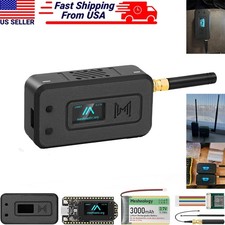
Heltec WiFi LoRa 32 V3 board (in Meshnology N33 case, powered by 3000 mAh pack)
-
Rotary encoder wired to GPIO 6 (CLK), GPIO 5 (DT), GPIO 4 (SW)
-
OLED display on I²C (SDA= 4, SCL= 15)
The sketch begins by including and initializing everything exactly as in Heltec_ESP32_LoRa_V3_Sevo_TX_AiRotaryEncoder.ino:
cppCopyEdit#include "AiEsp32RotaryEncoder.h"
#include "HT_SSD1306Wire.h"
#include "LoRaWan_APP.h"
#include "mbedtls/aes.h"
// …
static SSD1306Wire display(0x3c, 500000, SDA_OLED, SCL_OLED, GEOMETRY, RST_OLED);
AiEsp32RotaryEncoder rotaryEncoder = AiEsp32RotaryEncoder(
    PIN_A, PIN_B, SW_PIN, ROTARY_ENCODER_VCC_PIN, false, true, true);
const int homePosition = 90;
const int MAX_ANGLE    = 180;
int servoAngel = homePosition;
In setup(), the code:
-
Powers on the display, sets font
-
Calls
rotaryEncoder.begin(),rotaryEncoder.setup(readEncoderISR),rotaryEncoder.setBoundaries(0, MAX_ANGLE, true)androtaryEncoder.setAcceleration(20) -
Resets encoder to
homePosition -
Initializes LoRa via
Mcu.begin(HELTEC_BOARD, SLOW_CLK_TPYE)and sets upRadioEvents, channel, and parameters exactly as in the provided sketch.
2. Sending the angle securely
Every loop cycle runs rotary_loop(), which:
-
Reads the encoder in the ISR
-
When
servoAngelchanges, packages it into a 16-byte buffer, encrypts with AES-128 (encryptAES()from the sketch), and callscppCopyEditRadio.Send(data, sizeof(data)); -
Sets
lora_idle = falseuntilOnTxDone()fires and resets it.
3. Receiver (RX) hardware & setup
On the RX side you need:
-
Heltec WiFi LoRa 32 V3 board (same case/battery)
-
Micro-servo (e.g. SG90) on GPIO 6 (or any tested PWM pin)
-
OLED display
The sketch in Heltec_ESP32_LoRa_V3_Sevo_RX.ino starts with:
cppCopyEdit#include <ESP32Servo.h>
#include "HT_SSD1306Wire.h"
#include "LoRaWan_APP.h"
#include "mbedtls/aes.h"
// …
const int servoPin       = 6;
const int SERVO_DUTY_MIN = 400;  // us
const int SERVO_DUTY_MAX = 2400; // us
Servo    myservo;
int      servoAngel     = homePosition;
In setup(), it:
-
Powers on Vext for the display/LoRa module (
VextON()) -
Calls
Radio.Init(&RadioEvents)and configures RX with the same LoRa parameters -
Attaches the servo with
myservo.attach(servoPin, SERVO_DUTY_MIN, SERVO_DUTY_MAX)and centers it athomePosition.
4. Receiving, decrypting, and driving the servo
The core is the OnRxDone(uint8_t *payload, …) callback:
cppCopyEditdecryptAES((uint8_t*)rxpacket, userKey);
if (isNumber(rxpacket)) {
  servoAngel = atoi(rxpacket);
  myservo.write(servoAngel);
  delay(15);
}
Serial.println("Angle: " + String(servoAngel));
lora_idle = true;
It decrypts the 16-byte block, converts to an integer, and immediately updates the servo.
5. PWM pin support & servo tuning
We tested these ESP32 pins for PWM output and they all work for driving a micro-servo:
CopyEdit1, 2, 3, 4, 5, 6, 19, 35, 36, 38, 39, 40, 41, 42, 45, 47, 48
For a standard SG90, our code uses a pulse range of 400 µs (0°) to 2400 µs (180°), which gives a smooth, full sweep without jitter.
6. Wiring diagram
Below are placeholders where you can drop in your TX and RX schematics:


Code & Affiliate Links
All of the above sketches are available for download in the “Code & Resources†section below. If you’d like to build this yourself, please consider buying your Heltec LoRa32 V3 module, Meshnology N33 case, rotary encoder, and SG90 servo via our affiliate links. It costs you nothing extra and helps us keep making free tutorials like this!
Video Chapters for Reference
-
00:00 Introduction & Overview
-
00:05 Remote Control Concepts
-
00:19 LoRa Communication Basics
-
00:23 Hardware Preview
-
00:28 Case & Battery Showcase
-
01:03 Module Features
-
01:42 Specs & Connectivity
-
02:54 Powering the Servo
-
03:05 Wiring & Pinout
-
09:35 Antenna Placement
-
11:04 Case Assembly
-
29:26 Uploading Sketches
-
35:09 Range Test 1.2 km
-
36:38 Range Test 1.4 km
-
38:41 Performance Recap
-
43:04 Conclusion & Support
This tutorial is part of: WiFi LoRa 32 Tutorials
- Using Heltec WiFi LoRa 32 V3 to transmit temperature using DHT22 to 1.4km
- 13 Miles 20km with NO WiFi? How LoRa Sent Voltage Across Crazy Distances! (Heltec WiFi LoRa 32 V3)
- Turn On a Device from 13 mile 21km Away – The Ultimate Off-Grid LoRa Project with WiFi LoRa 32!
- Remote Door Alert System from 13 mile 21 km Away With LoRa – Off the Grid! (Heltec WiFi LoRa 32 V3)
- DIY Remote Relay Project: 13 Mile No-Wi-Fi/No-SIM Heltec LoRa 32 Module
- How to Use the Heltec LoRa CubeCell Development Board HTCC-AB01
/*
File: Heltec_ESP32_LoRa_V3_Sevo_TX_AiRotaryEncoder.ino
written on 24 Jun, 2025 by Ahmad Shamshiri

 * =====================================================================
 * ARDUINO CODE DESCRIPTION: SECURE LoRa SERVO CONTROL SYSTEM (TX)
 * =====================================================================
 *
 * HARDWARE COMPONENTS:
 * -------------------
 *  - Main Controller: Heltec WiFi LoRa 32 V3
 *  - Enclosure: Meshnology N33 case with 3000mAh battery
 *  - Input: Rotary encoder with push-button
 *  - Feedback: Built-in OLED display
 *  - Output: Servo motor + LoRa wireless transmission
 *
 * SYSTEM FUNCTIONALITY:
 * -------------------
 * [1] ROTARY ENCODER CONTROL:
 *     - Clockwise/Counter-clockwise rotation adjusts target angle (0°-180°)
 *     - Real-time angle display on OLED screen
 *     - Push-button returns servo to Home position (default: 90°)
 *
 * [2] SECURE WIRELESS TRANSMISSION:
 *     - All angle values encrypted before LoRa transmission
 *     - Home position command transmitted as special secure packet
 *     - Uses 433MHz LoRa band for reliable communication
 *
 * [3] POWER MANAGEMENT:
 *     - Optimized for battery operation (3000mAh)
 *     - Low-power modes between transmissions
 *
 * FOR COMPLETE SETUP INSTRUCTIONS:
 * Please watch the tutorial video at: https://youtu.be/EPynuJ7sasY
 * =====================================================================

Watch full video explaination:  https://youtu.be/EPynuJ7sasY
Resources page: https://robojax.com/T635


 * DISCLAIMER:
 * This code is provided "AS IS" without warranty of any kind. The author
 * shall not be held liable for any damages arising from the use of this code.
 *
 * LICENSE:
 * This work is licensed under the GNU General Public License v3.0
 * Permissions beyond the scope of this license may be available at Robojax.com
 *
 * SHARING TERMS:
 * You are free to share, copy and modify this code for non-commercial purposes
 * PROVIDED you:
 * 1. Keep this entire comment block intact with the original code
 * 2. Include the original Robojax.com link
 * 3. Keep the YouTube tutorial link (if applicable)
 * 4. Clearly indicate any modifications made
 *
 * Original tutorial at: https://robojax.com/T635
 * YouTube Video: https://youtu.be/EPynuJ7sasY
 *
 * ********************************************************************
 */

#include <Wire.h>
#include "HT_SSD1306Wire.h"
#include "WiFi.h"
static SSD1306Wire  display(0x3c, 500000, SDA_OLED, SCL_OLED, GEOMETRY_128_64, RST_OLED); // addr , freq , i2c group , resolution , rst


const int TX_POWER = 2;//dBm from 2 to 20. when powered via battery 2 to 14dBm is the best option
const int MAX_ANGLE = 180;//the most common is 180, but you can set it as needed

String labelAngle = "Angle";
const int homePosition = 90; //initial position


//endcoder
const int SW_PIN = 4;//define a pin for rotary encode switch
const int PIN_A  = 6;
const int PIN_B  = 5;//
const int ANGLE_STEP  = 6;//
const bool debug= false;//to print debug data in serial moinitor set it to true, else false

int servoAngel = homePosition;
int oldAngleValue = servoAngel;
#include "mbedtls/aes.h"//for securing data
#include <cstring>  // For memset, memcpy
mbedtls_aes_context aes;
const char *userKey = "hyhT676#h~_1a"; //Security key.


#include "LoRaWan_APP.h"
#include "AiEsp32RotaryEncoder.h"
#include "Arduino.h"
#define ROTARY_ENCODER_VCC_PIN -1

//instead of changing here, rather change numbers above
AiEsp32RotaryEncoder rotaryEncoder = AiEsp32RotaryEncoder(
            PIN_A,
            PIN_B,
            SW_PIN,
            ROTARY_ENCODER_VCC_PIN,
            ANGLE_STEP);


#define RF_FREQUENCY                                915432000 // Hz

#define TX_OUTPUT_POWER                             TX_POWER        // dBm from 2 to 20. when powered via battery 2 to 14dBm

#define LORA_BANDWIDTH                              0         // [0: 125 kHz,
                                                              //  1: 250 kHz,
                                                              //  2: 500 kHz,
                                                              //  3: Reserved]
#define LORA_SPREADING_FACTOR                       7         // [SF7..SF12]
#define LORA_CODINGRATE                             1         // [1: 4/5,
                                                              //  2: 4/6,
                                                              //  3: 4/7,
                                                              //  4: 4/8]
#define LORA_PREAMBLE_LENGTH                        8         // Same for Tx and Rx
#define LORA_SYMBOL_TIMEOUT                         0         // Symbols
#define LORA_FIX_LENGTH_PAYLOAD_ON                  false
#define LORA_IQ_INVERSION_ON                        false


#define RX_TIMEOUT_VALUE                            1000
#define BUFFER_SIZE                                 64 // Define the payload size here

char txpacket[BUFFER_SIZE];
char rxpacket[BUFFER_SIZE];

double txNumber;

bool lora_idle=true;

static RadioEvents_t RadioEvents;
unsigned long lastTxTime = 0;
void OnTxDone( void );
void OnTxTimeout( void );
void decryptAES(uint8_t *data, const char *key);
void encryptAES(uint8_t *data, const char *key);
void processKey(const char *userKey, uint8_t *processedKey, size_t keySize);
void VextON(void);

void rotary_loop();//prototyp function: rotary encoder
void IRAM_ATTR readEncoderISR();//prototyp function: rotary encoder
void rotary_onButtonClick();//prototyp function: rotary encoder

void setup() {
  Serial.begin(115200);
  Serial.println();

  VextON();
  delay(100);

	//we must initialize rotary encoder
	rotaryEncoder.begin();
	rotaryEncoder.setup(readEncoderISR);
	bool circleValues = false;
	rotaryEncoder.setBoundaries(0, MAX_ANGLE, circleValues); //minValue, maxValue, circleValues true|false (when max go to min and vice versa)
	/*Rotary acceleration introduced 25.2.2021.
   * in case range to select is huge, for example - select a value between 0 and 1000 and we want 785
   * without accelerateion you need long time to get to that number
   * Using acceleration, faster you turn, faster will the value raise.
   * For fine tuning slow down.
   */
	//rotaryEncoder.disableAcceleration(); //acceleration is now enabled by default - disable if you dont need it
	rotaryEncoder.setAcceleration(20); //or set the value - larger number = more accelearation; 0 or 1 means disabled acceleration
  rotaryEncoder.reset(homePosition); //set home position

  // Initialising the UI will init the display too.
  display.init();
  display.setFont(ArialMT_Plain_10);
  //LoRa stuff
  Mcu.begin(HELTEC_BOARD,SLOW_CLK_TPYE);

    txNumber=0;

    RadioEvents.TxDone = OnTxDone;
    RadioEvents.TxTimeout = OnTxTimeout;

    Radio.Init( &RadioEvents );
    Radio.SetChannel( RF_FREQUENCY );
    Radio.SetTxConfig( MODEM_LORA, TX_OUTPUT_POWER, 0, LORA_BANDWIDTH,
                                   LORA_SPREADING_FACTOR, LORA_CODINGRATE,
                                   LORA_PREAMBLE_LENGTH, LORA_FIX_LENGTH_PAYLOAD_ON,
                                   true, 0, 0, LORA_IQ_INVERSION_ON, 3000 );

}


void displayAngle() {
    display.clear();  // Clear display before new content

    // Line 1: Text: Angle
    display.setTextAlignment(TEXT_ALIGN_LEFT);

    // Line 2: Temperature value in 24pt font
    display.setFont(ArialMT_Plain_24);

    // Format
    String angleString = String(servoAngel) + "°"; //

    display.setFont(ArialMT_Plain_16);
    display.drawString(0, 0, labelAngle);
    display.setFont(ArialMT_Plain_24);
    display.drawString(0, 15, angleString);

    display.display();  // Update OLED
}


void VextON(void)
{
  pinMode(Vext,OUTPUT);
  digitalWrite(Vext, LOW);
}

void VextOFF(void) //Vext default OFF
{
  pinMode(Vext,OUTPUT);
  digitalWrite(Vext, HIGH);
}

void sendData()
{

  String txData = String(servoAngel) ;

  uint8_t data[BUFFER_SIZE];
  memset(data, 0, sizeof(data));  // Zero-padding
  strncpy((char*)data, txData.c_str(), sizeof(data) - 1); // Copy string safely

  encryptAES(data, userKey);  // Encrypt before sending
  if(lora_idle == true)
    {
      //delay(1000);
      Radio.Send(data,  sizeof(data));
      if(debug){
      Serial.print("Sending: ");
      Serial.println((char *)data);
      }
      lora_idle = false;
      oldAngleValue =servoAngel;//keep record of angle change
    }
    Radio.IrqProcess( );
}


void loop() {
  rotary_loop();
  // clear the display
  display.clear();

  displayAngle(); //

  if(oldAngleValue != servoAngel)
  {
	  sendData();
  }
  //delay(100);

}


void OnTxDone( void )
{
        if(debug){
	        Serial.println("TX done......");
        }
	lora_idle = true;
}

void OnTxTimeout( void )
{
    Radio.Sleep( );
        if(debug){
	        Serial.println("TX Timeout......");
        }
    lora_idle = true;
}


/**
 * Converts a user-provided plaintext key into a fixed-length 16-byte (128-bit)
 * or 32-byte (256-bit) key.
 */
void processKey(const char *userKey, uint8_t *processedKey, size_t keySize) {
    memset(processedKey, 0, keySize); // Fill with zeros
    size_t len = strlen(userKey);
    if (len > keySize) len = keySize; // Truncate if too long
    memcpy(processedKey, userKey, len); // Copy valid key part
}

/**
 * Encrypts a 16-byte (one block) message using AES-128.
 */
void encryptAES(uint8_t *data, const char *key) {
    uint8_t processedKey[16]; // 128-bit key
    processKey(key, processedKey, 16);

    mbedtls_aes_init(&aes);
    mbedtls_aes_setkey_enc(&aes, processedKey, 128);
    mbedtls_aes_crypt_ecb(&aes, MBEDTLS_AES_ENCRYPT, data, data);
    mbedtls_aes_free(&aes);
}

/**
 * Decrypts a 16-byte (one block) message using AES-128.
 */
void decryptAES(uint8_t *data, const char *key) {
    uint8_t processedKey[16]; // 128-bit key
    processKey(key, processedKey, 16);

    mbedtls_aes_init(&aes);
    mbedtls_aes_setkey_dec(&aes, processedKey, 128);
    mbedtls_aes_crypt_ecb(&aes, MBEDTLS_AES_DECRYPT, data, data);
    mbedtls_aes_free(&aes);
}


void rotary_onButtonClick()
{
	static unsigned long lastTimePressed = 0;
	//ignore multiple press in that time milliseconds
	if (millis() - lastTimePressed < 500)
	{
		return;
	}
	lastTimePressed = millis();

	        if(debug){
	          Serial.print("button pressed ");
	          Serial.print(millis());
	          Serial.println(" milliseconds after restart");
          }
}

void rotary_loop()
{
	//dont print anything unless value changed
	if (rotaryEncoder.encoderChanged())
	{
		        if(debug){
	            Serial.print("Value: ");
		          Serial.println(rotaryEncoder.readEncoder());
            }
    servoAngel = rotaryEncoder.readEncoder();

	}
	if (rotaryEncoder.isEncoderButtonClicked())
	{
    rotaryEncoder.reset(homePosition);
    servoAngel = homePosition;
		rotary_onButtonClick();
	}
}

void IRAM_ATTR readEncoderISR()
{
	rotaryEncoder.readEncoder_ISR();
}
Common Course Links
Common Course Files
Resources & references
-
ExternalHeltec WiFi Kit 32 website linkheltec.org
Files📁
No files available.