Lesson 98-10: Arduino Traffic Light
Traffic lights are one of those everyday systems we rarely think about — until we build one. In this project, you'll use an Arduino to simulate a real traffic light sequence: green on, then yellow, then red, each for its own configurable duration, repeating endlessly. It's a perfect beginner project because it teaches sequential timing logic, multi-output control, and the relationship between what you write in code and what you see in the physical world.

Beyond the classroom demo, the timing logic you learn here shows up everywhere:
- Building a realistic traffic light model for a model railroad or diorama
- Creating a timed indicator system for a workshop or garage (e.g., "safe to enter" / "wait" signals)
- Learning the foundation for pedestrian crossing signals with button-triggered phases
- Prototyping a timed relay sequence for industrial or home automation tasks
- Teaching kids about sequencing, timing, and electronics with a familiar, recognizable object
The best part: the whole thing runs standalone once uploaded. You program the Arduino once from your computer, then power it from a battery or adapter and it works forever — no PC required (in video at 12:27).
How the Traffic Light Works
A traffic light is really just a timed sequence of three outputs. The Arduino turns on one LED at a time, waits a set number of seconds, turns it off, and moves to the next. The cycle then repeats. In the video's example timing, green stays on for 3 seconds, yellow for 1 second, and red for 3 seconds — but all of these are adjustable in code (in video at 49:44).
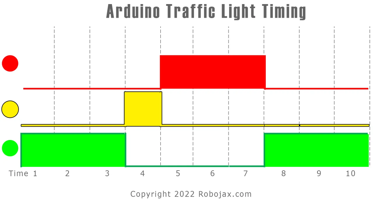

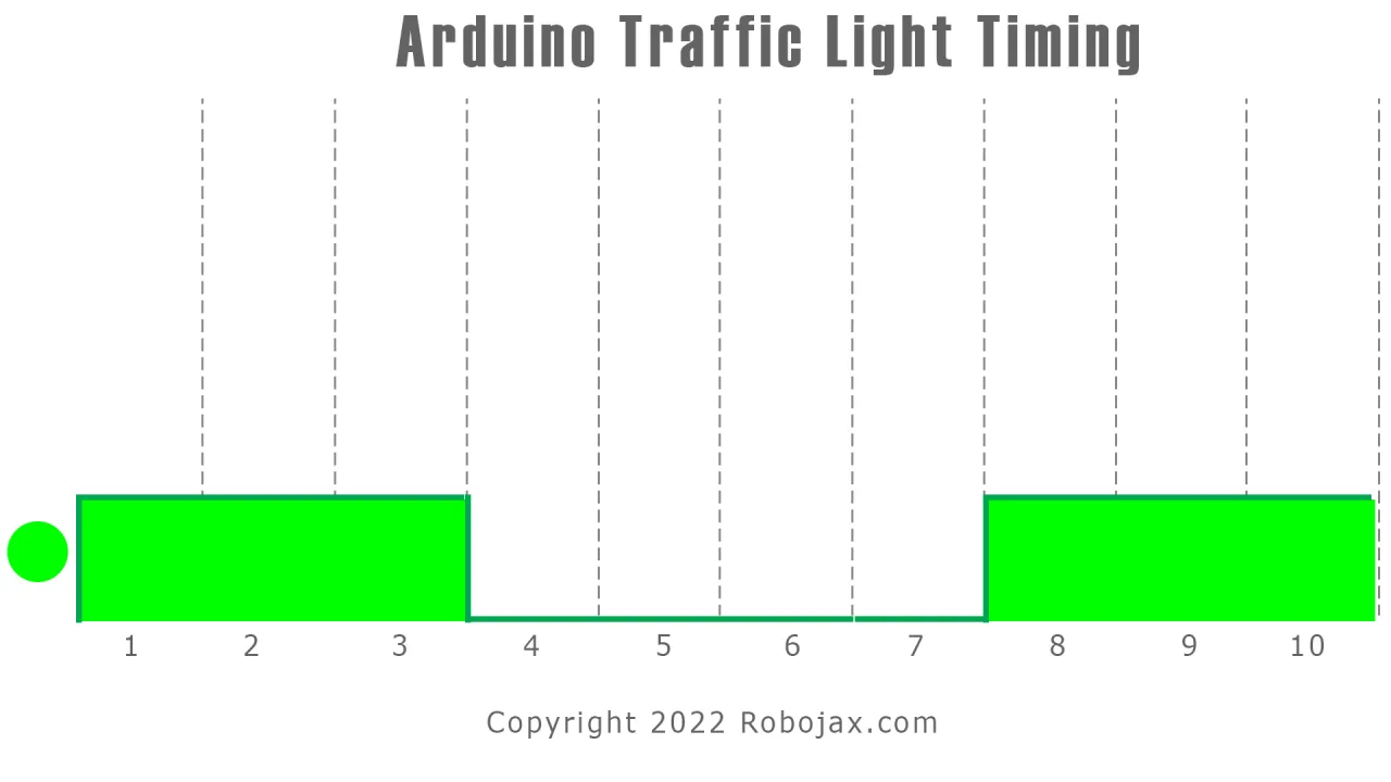
The reason the sequence feels realistic is that the durations mirror real-world traffic flow: green and red are longer because vehicles need time to move through the intersection, while yellow is short because it's only a transition warning. You can tune these to match any scenario you like.
Hardware and Components
The parts list for this project is minimal:
- 1 × Arduino board (Uno, Nano, or Mega — anything with at least 3 digital pins)
- 3 × LEDs (red, yellow/orange, and green — different colors make the effect obvious)
- 3 × resistors (300 Ω to 1 kΩ works well; the video uses 1 kΩ)
- 1 × breadboard
- Jumper wires
- Optional: a lithium-ion battery or 5 V power adapter to run it standalone
The video recommends using three distinctly colored LEDs so the traffic light effect is immediately visible — otherwise you'd have to label them (in video at 02:04).
Understanding LED Current Limiting
Every LED needs a current-limiting resistor in series. Here's why: an LED has a nearly fixed forward voltage (typically around 2 V for standard 5 mm LEDs), and if you connect it directly to 5 V, the current will spike and destroy it. The resistor absorbs the excess voltage.
Using Ohm's law, if the LED drops 2 V and the supply is 5 V, then 3 V must drop across the resistor. With a target current of about 10 mA, the resistor value works out to roughly 300 Ω (in video at 04:41). In practice, anything from 300 Ω up to 1 kΩ will work — higher values simply make the LED dimmer.
Wiring Guide
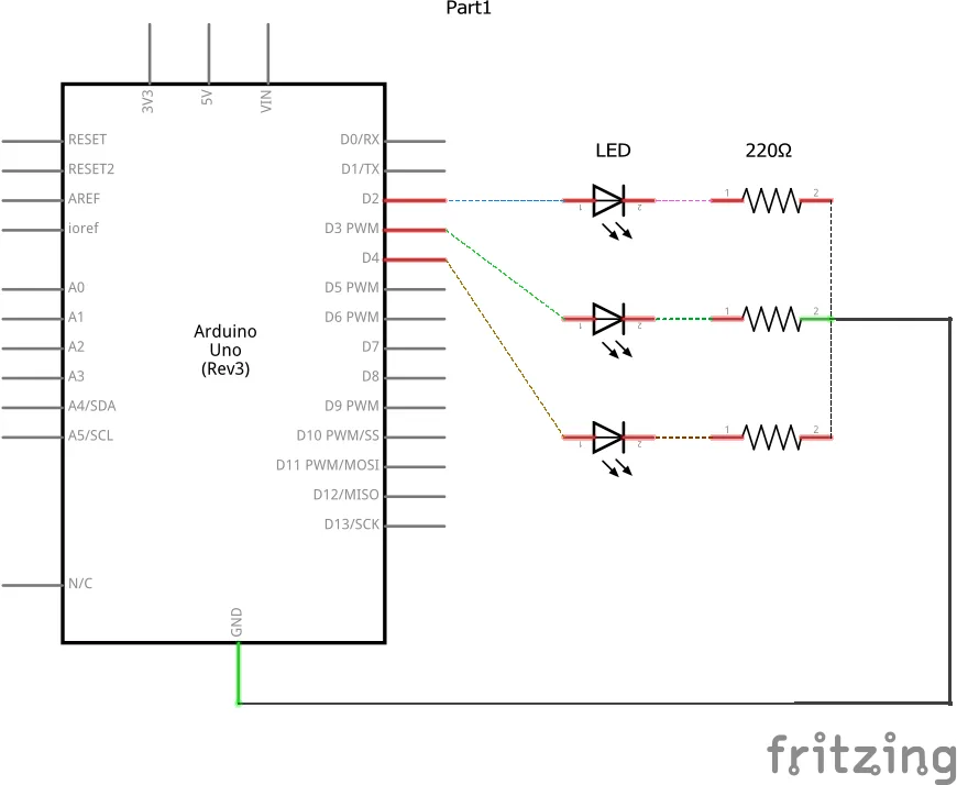

Each LED is wired identically: the anode (longer leg) connects to an Arduino digital pin, and the cathode (shorter leg, flat side of the LED body) connects through a resistor to ground.
In the video's wiring, the red LED connects to pin 2, the yellow/orange LED to pin 3, and the green LED to pin 4 (in video at 50:50). All three resistors share a common ground rail on the breadboard. The order of colors on the breadboard doesn't matter — what matters is that the pin numbers in your code match the pins you actually used.
One handy tip from the video: the resistor can go on either side of the LED. You can place it between the Arduino pin and the LED anode, or between the LED cathode and ground — electrically it's the same (in video at 51:52).
Code Explanation
The full program is available below the article. Here we'll focus on the parts you'll want to customize.
At the top of the sketch, three pin definitions map each LED to a digital pin. If you wired your LEDs to different pins, change these values:
const int greenLED = 4;
const int yellowLED = 3;
const int redLED = 2;
Next come the timing constants. These control how long each light stays on, in milliseconds. The video uses 5000 ms for green, 1000 ms for yellow, and 5000 ms for red by default — but during the demo these were changed to 3 s / 1 s / 3 s, and later to 10 s / 3 s / 10 s (in video at 56:27):
const int greenOnTime = 5000;
const int yellowOnTime = 1000;
const int redOnTime = 5000;
To change the rhythm of your traffic light, just edit these three values. Want a slow, realistic intersection? Try 10000, 3000, 10000. Want a fast demo? Try 1000, 300, 1000.
Inside loop(), the sequence is straightforward: turn green on, wait, turn green off; turn yellow on, wait, turn yellow off; turn red on, wait, turn red off; then loop back to green. The serial monitor prints each state change so you can verify the timing matches what you expect.
Live Demonstration
Once the code is uploaded, the Arduino runs the cycle on its own. In the video, the green LED lights first, then after its duration the yellow comes on briefly, then red, and the cycle restarts immediately (in video at 55:20).
The serial monitor mirrors this in text — "green LED on", "green off", "yellow on", and so on — which is a great way to confirm your timing values are working as intended. When you're ready to run it untethered, disconnect USB and connect a lithium-ion battery or 5 V adapter; the Arduino will keep cycling without a computer (in video at 56:11).
Related projects from this video
- Lesson 98-1: How to Turn On and Off an LED with Arduino
- Lesson 98-2: How to Turn On and Off an LED Using a Push Button with Arduino
- Lesson 98-3: How to Turn On/Off a Toggle LED Using a Push Button with Arduino
- Lesson 98-4: Fading an LED Light Using Arduino: Brightness Control
- Lesson 98-5: Fade Light When a Button Is Pressed Using Arduino
- Lesson 98-6: Seesaw LED Game with Arduino
- Lesson 98-7: Walking Light Using Arduino and 5 LEDs
- Lesson 98-8: Walking Light with Push Button and LEDs with Arduino
- Lesson 98-9: LED Voltage Level Meter Using Arduino or walking light with potentiometer
Chapters
- [00:00] Overview of the 10 Arduino LED projects
- [01:22] Introduction to the Arduino step-by-step course
- [02:29] What is an LED: symbol, anode, and cathode
- [03:49] Calculating the LED current-limiting resistor
- [49:25] Introduction to the traffic light project
- [49:44] Traffic light timing explained
- [50:34] Wiring diagram for the traffic light
- [52:13] Code explanation for the traffic light
- [54:32] Live demonstration with serial monitor
- [55:30] Changing the timing values
- [56:11] Running the traffic light on battery power
Hotuna
This code has not been parsed yet. Please return to the admin panel to parse it.Abin da zaka iya bukata
-
AmazonSunFounder Arduino Learning Kit on AliExpresss.click.aliexpress.com
-
Amazon
-
Amazon
-
Amazon
Albarkatun da kuma shafukan da za a duba
-
TakarduDocumentation for SunFounder 3 in 1 IoT/Smart Car/Learning Kitdocs.sunfounder.com
-
Waje
-
Waje
Fayiloli📁
Littattafan Arduino (zip)
-
SunFounder's 3-in-1 Smart Car learning kit source code
3in1-kit-main-v2.zip12.80 MB
Jagoran Mai Amfani
-
Littafin hada motar SunFounder 3-in-1 Arduino Smart CarWannan takarda tana nuna yadda ake hada SunFounder 3-in-1 Arduino Smart Car mataki-mataki
SunFounder_car_assembly_manual.pdf1.20 MB