Lesson 98-1: How to Turn On and Off an LED with Arduino
Blinking an LED is the "Hello, World!" of electronics, and for good reason: it teaches you the complete workflow of an Arduino project — wiring a component safely, writing code, uploading it, and watching your instructions become physical action. In this tutorial you will build a circuit that turns a single LED on and off automatically, with the on-time and off-time controlled entirely by two numbers in your code. Once you understand this pattern, you can reuse it for almost anything: a status indicator that pulses when a device is running, a night-light timer, a warning beacon, a "heartbeat" LED that shows a program is alive, or the first stage of a larger project like a traffic light or LED chaser.

This lesson is the first of ten LED projects in the video, so we will focus only on the simplest one: turning an LED on and off directly from an Arduino pin. The push-button, fading, seesaw, walking-light, voltage-meter, and traffic-light builds that follow are each covered in their own separate tutorials, linked throughout this article and collected at the end.
Why Start with an LED?
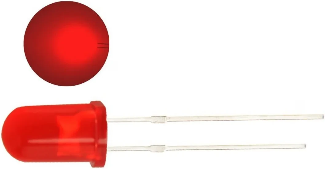
An LED (light-emitting diode) is a diode that emits light when current flows through it in the correct direction. It has two legs: the anode (positive, the longer leg) and the cathode (negative, the shorter leg, marked by the flat edge on the plastic rim). Current must flow from anode to cathode — connect it backwards and nothing lights up, but no damage occurs.
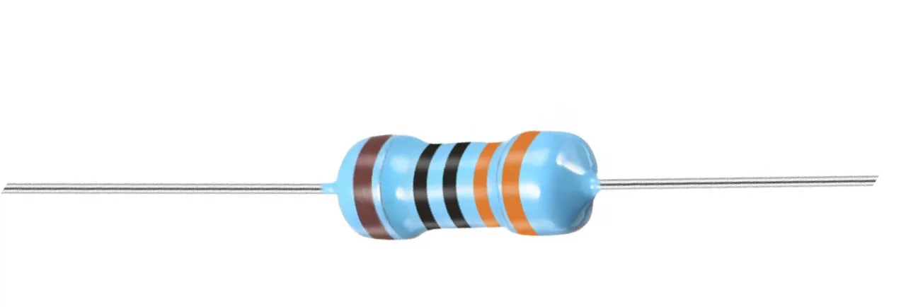
An LED cannot be connected directly across 5 V. Its forward operating voltage is roughly 2 V, so the remaining 3 V must be dropped somewhere — and that is the job of a series resistor (in video at 03:49). Using Ohm's law, with a typical LED current of about 10 mA, the resistor works out to roughly 300 Ω. In practice anything from 300 Ω to 1000 Ω will work: the higher the value, the dimmer the LED, because less current flows. The resistor is not optional — without it, the LED will draw excessive current and burn out.
Hardware and Components
- Arduino board (Uno, Nano, or Mega — any will work)
- One LED (5 mm or 3 mm, any color)
- One resistor between 300 Ω and 1000 Ω (the video uses 1 kΩ)
- Breadboard
- Dupont jumper wires
- USB cable for programming (a battery or 5 V adapter can power it afterwards)
Wiring Guide
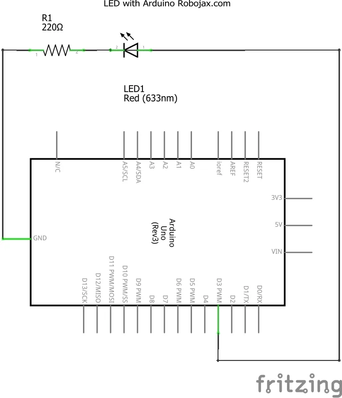

The circuit is deliberately minimal. The LED's anode connects to Arduino digital pin 3, and the cathode connects through the resistor to the Arduino's GND rail. Because the resistor sits between the cathode and ground, it limits current no matter which pin state the Arduino drives.
The video uses Fritzing, a free tool available from fritzing.org, to draw the breadboard layout and schematic (in video at 06:04). If you want to document or plan your own circuits, it is a handy companion to this course.
Code Explanation
The sketch defines a few values at the top that you are meant to change. Everything below them is the standard setup() and loop() structure.
const int LEDPin = 3;//define a pin that is connected to LED

const int ON_TIME = 2000;
const int OFF_TIME = 500;
LEDPin — the digital pin the LED's anode is wired to. Change this if you move the wire to a different pin.
ON_TIME — how long, in milliseconds, the LED stays lit. The default 2000 equals two seconds. For a half-second blink, set it to 500.
OFF_TIME — how long the LED stays dark between blinks. The default 500 is half a second.
Both values are declared const, meaning the program cannot change them while running — they are configuration, not variables. The setup() function runs once and configures pin 3 as an output, drives it low so the LED starts off, and opens the serial monitor at 9600 baud so you can watch status messages. The loop() then repeats forever: set the pin high (LED on), print "Light ON", wait ON_TIME, set the pin low (LED off), print "Light OFF", wait OFF_TIME, and start over.
One important habit: after uploading, open the Serial Monitor (Tools → Serial Monitor, or Ctrl+Shift+M) and confirm the baud rate is set to 9600 — otherwise the text will appear as garbage (in video at 10:19).
Live Demonstration
The video walks through the full cycle: connect the Arduino over USB, upload the sketch, and watch the LED alternate on and off while the serial monitor logs each transition. The key takeaway is that once programmed, the Arduino no longer needs the computer — disconnect the USB and power the board from a battery or 5 V adapter, and it will keep blinking on its own (in video at 12:27).

Try changing ON_TIME to 200 and OFF_TIME to 200 for a fast blink, or make the on and off times very different to create a heartbeat-style pattern. This same on/off timing logic is the foundation of the later projects in the video series.
Adding a push button so you can control the LED by hand is covered in Lesson 98-2: How to Turn On and Off an LED Using a Push Button with Arduino.
Making the button latch the LED on and off with each press is covered in Lesson 98-3: How to Turn On/Off a Toggle LED Using a Push Button with Arduino.
Gradually dimming the LED with PWM is covered in Lesson 98-4: Fading an LED Light Using Arduino: Brightness Control.
Triggering a fade from a button press is covered in Lesson 98-5: Fade Light When a Button is Pressed Using Arduino.
Alternating two LEDs like a seesaw is covered in Lesson 98-6: See saw LED Game with Arduino.
Chasing a light across five LEDs is covered in Lesson 98-7: Walking Light Using Arduino and 5 LEDs.
Advancing the walking light with a button is covered in Lesson 98-8: Walking Light with Push Button and LEDs with Arduino.
Using LEDs as a voltage bar driven by a potentiometer is covered in Lesson 98-9: LED Voltage Level Meter Using Arduino or walking light with potentiometer.
Simulating a traffic signal with three LEDs is covered in Lesson 98-10: Arduino Traffic Light.
Related projects from this video
- Lesson 98-2: How to Turn On and Off an LED Using a Push Button with Arduino
- Lesson 98-3: How to Turn On/Off a Toggle LED Using a Push Button with Arduino
- Lesson 98-4: Fading an LED Light Using Arduino: Brightness Control
- Lesson 98-5: Fade Light When a Button is Pressed Using Arduino
- Lesson 98-6: See saw LED Game with Arduino
- Lesson 98-7: Walking Light Using Arduino and 5 LEDs
- Lesson 98-8: Walking Light with Push Button and LEDs with Arduino
- Lesson 98-9: LED Voltage Level Meter Using Arduino or walking light with potentiometer
- Lesson 98-10: Arduino Traffic Light
Chapters
- [00:00] Overview of the 10 LED projects
- [01:00] Introduction to the Arduino step-by-step course
- [02:29] How an LED works: anode, cathode, and symbol
- [03:49] Calculating the LED series resistor with Ohm's law
- [05:53] Project 1: Turning an LED on and off
- [06:04] Wiring diagram and Fritzing
- [08:50] Code walkthrough: pin, on-time, and off-time
- [10:19] Opening the Serial Monitor and uploading
- [12:27] Running the Arduino without a computer
- [12:43] Push button project preview
- [19:41] Toggle LED demonstration
- [20:12] Fading an LED with the built-in example
- [27:32] See saw LED project
- [30:47] Walking light with five LEDs
- [36:41] Walking light controlled by push button
- [42:25] LED voltage bar with potentiometer
- [49:25] Arduino traffic light
- [57:16] Closing remarks
Images


This code has not been parsed yet. Please return to the admin panel to parse it.Things you might need
-
AmazonSunFounder Arduino Learning Kit on AliExpresss.click.aliexpress.com
-
Amazon
-
Amazon
-
Amazon
Resources & references
-
DocumentationDocumentation for SunFounder 3 in 1 IoT/Smart Car/Learning Kitdocs.sunfounder.com
-
External
-
External
-
External
Files📁
Arduino Libraries (zip)
-
SunFounder's 3-in-1 Smart Car learning kit source code
3in1-kit-main-v2.zip12.80 MB
User’s Manual
-
SunFounder 3-in-1 Arduino Smart Car assembly manualThis document shows step by step assembly of SunFounder 3-in-1 Arduino Smart Car
SunFounder_car_assembly_manual.pdf1.20 MB