Lesson 98-8: Walking Light with Push Button and LEDs with Arduino
This project shows you how to build a "walking light" that advances one step every time you press a push button. Instead of a light that runs on its own timer, you get direct, tactile control: each press moves the illuminated LED one position forward, and after the last LED it wraps back around to the first. This is one of the most useful building blocks in Arduino learning, because it teaches you how to combine a digital input (the button) with a rotating state machine (which LED is currently lit) — a pattern you will reuse constantly.
Once you understand this pattern, the same logic powers a huge range of real projects. Here are a few practical ideas you can build with it:
- A menu selector on a device where each press highlights the next option.
- A sequential step indicator for a machine or process (step 1, step 2, step 3...).
- A score or level display you advance manually with a button.
- A "next channel" or "next mode" indicator for a lighting controller.
- A simple game or quiz buzzer where players take turns lighting the next lamp.
- A relay or load sequencer where each press activates the next output in order.
The key advantage over an automatic running light is control: nothing happens until you press, so the light only advances when you decide. The video also notes that the same toggling and sequencing idea can drive a relay to switch an AC light or control a motor, not just LEDs (in video at 19:52).
Hardware and Components
The parts list is short and inexpensive:
- An Arduino board (Uno, Nano, Mega, or any compatible board).
- Five LEDs — 5 mm or 3 mm, any colors you like.
- Five current-limiting resistors, 200 Ω to 1000 Ω (the video uses 1 kΩ).
- One push button switch (a momentary tactile switch is ideal).
- A breadboard and some DuPont jumper wires.
A quick note on the LEDs: the cathode is the shorter leg and the side with the flat edge, while the anode is the longer leg (in video at 03:13). The resistor value is not critical — a higher resistor simply makes the LED dimmer, so anything from about 300 Ω up to 1000 Ω will work fine (in video at 05:33).
Wiring Guide

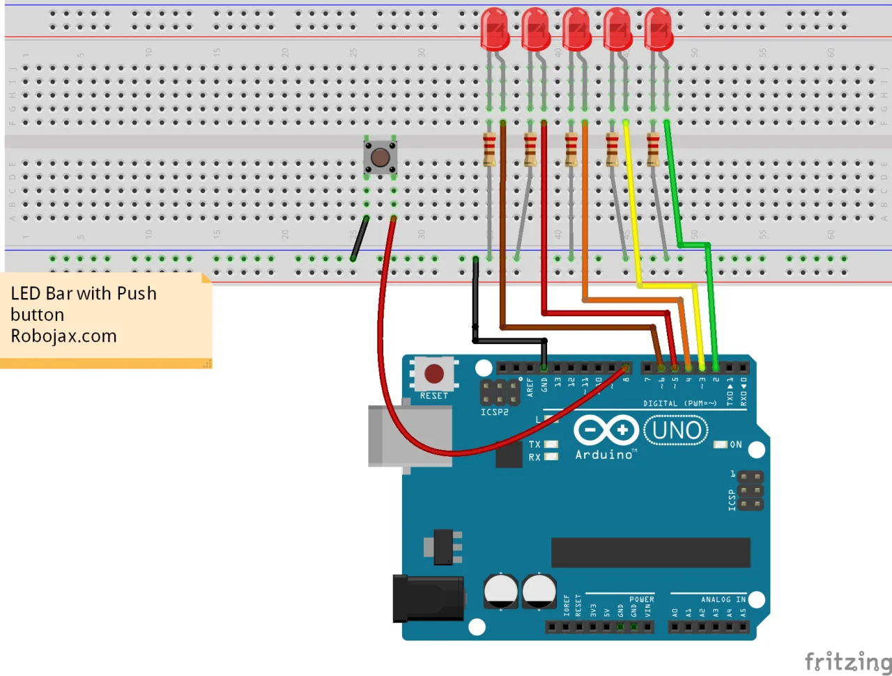
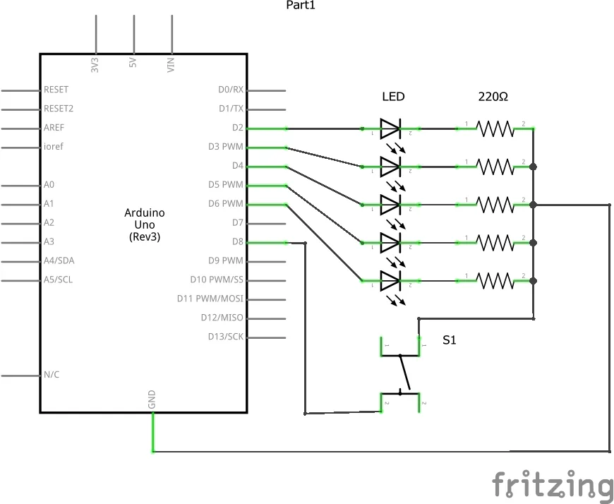
The wiring is essentially the same as a standard five-LED walking light, with one push button added. Each LED's anode connects to its own Arduino pin, and each cathode connects through its own resistor to a shared ground rail on the breadboard. In this build the LEDs are wired to pins 3, 4, 5, 6, and 7 (in video at 31:37). The push button is placed on the breadboard with one leg to ground and the other leg to pin 2 — the same pin the code uses for the button (in video at 37:04).
Because the code enables the Arduino's internal pull-up resistor, no external resistor is needed on the button. When the button is not pressed the pin reads HIGH, and when you press it the pin is pulled to ground and reads LOW (in video at 14:02).
Code Explanation
The full program is available below this article. Here we focus on the parts you will actually want to change.
At the top of the sketch, each LED and the button are assigned to a pin. This is where you customize the build to match your own wiring:
const int pushButtonPin = 2; // push button pin
const int LED1 = 3;
const int LED2 = 4;
const int LED3 = 5;
const int LED4 = 6;
const int LED5 = 7;

int LED_ON = LED1; // which LED is currently lit
The LED_ON variable is the heart of the project. It remembers which LED is currently illuminated, starting at LED1. Every time you press the button, the code advances LED_ON to the next LED in the sequence and turns the previous one off, so only one LED is ever lit at a time.
There is also a small delay after each press:
delay(200); // debounce / give the user time between pressesThis 200 millisecond pause prevents a single physical press from registering as multiple presses. If your finger shakes or the button feels too sensitive, increase this number; if you want faster response, lower it. Be aware that setting it too low can make the light skip ahead unexpectedly (in video at 41:20).
The main logic lives in the loop(). It reads the button, and only when the button is pressed (reading LOW) does it advance the light. The sequence uses a chain of if / else if checks to move from LED1 to LED2 to LED3, and so on, wrapping back to LED1 after the last one. If you want to change the direction or the order of the LEDs, this is the block to edit — simply reassign which pin follows which.
Live Project and Demonstration
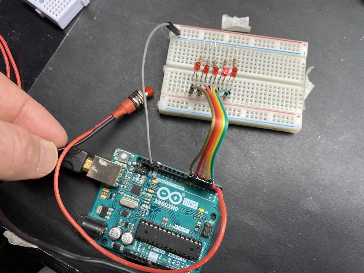
After uploading the code, pressing the button lights the first LED; releasing it leaves that LED on. The next press moves the light to the second LED, then the third, fourth, and fifth, and the following press returns to the first — a continuous rotation (in video at 40:22).
A nice side effect of the 200 millisecond delay is that if you hold the button down, the light keeps advancing on its own every 200 milliseconds, effectively turning the project into an automatic walking light while the button is held (in video at 42:07). Release the button and it stops on the current LED. This gives you both manual stepping and hands-free running from a single button.
If you would rather have the light run automatically without any button at all, that is a separate build. The automatic version is covered in Lesson 98-7: Walking Light Using Arduino and 5 LEDs.
Related projects from this video
- Lesson 98-1: How to Turn On and Off an LED with Arduino
- Lesson 98-2: How to Turn On and Off an LED Using a Push Button with Arduino
- Lesson 98-3: How to Turn On/Off a Toggle LED Using a Push Button with Arduino
- Lesson 98-4: Fading an LED Light Using Arduino: Brightness Control
- Lesson 98-5: Fade Light When a Button Is Pressed Using Arduino
- Lesson 98-6: Seesaw LED Game with Arduino
- Lesson 98-7: Walking Light Using Arduino and 5 LEDs
- Lesson 98-9: LED Voltage Level Meter Using Arduino or walking light with potentiometer
- Lesson 98-10: Arduino Traffic Light
Chapters
- [00:00] Overview of the 10 Arduino LED projects
- [01:22] Introduction to the Arduino step-by-step course
- [02:29] Understanding LEDs: symbols, polarity and pins
- [03:49] Calculating the LED current-limiting resistor
- [30:47] Walking light with 5 LEDs: wiring and principle
- [32:52] Walking light code: pins, timing and loop
- [36:41] Advancing the light with a push button
- [37:44] Walking light with push button: code walkthrough
- [40:22] Demonstration and adjusting the press delay
- [57:16] Closing remarks and course outro
Images
This code has not been parsed yet. Please return to the admin panel to parse it.Things you might need
-
AmazonSunFounder Arduino Learning Kit on AliExpresss.click.aliexpress.com
-
Amazon
-
Amazon
-
Amazon
Resources & references
-
DocumentationDocumentation for SunFounder 3 in 1 IoT/Smart Car/Learning Kitdocs.sunfounder.com
-
External
-
External
-
External
Files📁
Arduino Libraries (zip)
-
SunFounder's 3-in-1 Smart Car learning kit source code
3in1-kit-main-v2.zip12.80 MB
User’s Manual
-
SunFounder 3-in-1 Arduino Smart Car assembly manualThis document shows step by step assembly of SunFounder 3-in-1 Arduino Smart Car
SunFounder_car_assembly_manual.pdf1.20 MB