Lesson 98-2: How to Turn On and Off an LED Using a Push Button with Arduino
This project shows you how to control an LED with a push button using an Arduino. Instead of letting the LED blink on its own, you decide when it lights up: hold the button down and the LED turns on, let go and it turns off. It is the natural next step after a plain blink sketch, because it introduces two ideas that appear in almost every Arduino project you will ever build — reading a digital input, and using that input to make a decision in code.
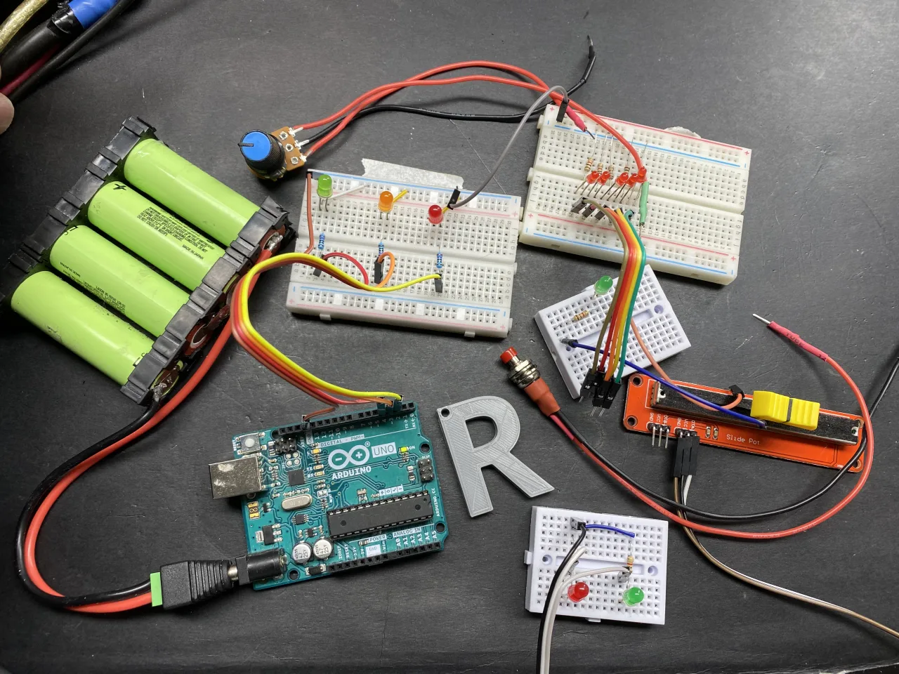
The real value here is learning how a microcontroller senses the physical world. A push button is the simplest human input device there is, but the same pattern — read an input, test a condition, drive an output — is exactly how you would read a limit switch on a 3D printer, detect a door opening on a security system, or start a motor from a control panel. Once you understand this one circuit, you can swap the LED for almost anything.
Here are some practical things you can build with the same technique:
- A momentary doorbell or call button that lights a lamp while pressed.
- A "dead man's switch" that only keeps a relay (and whatever it powers) energized while the button is held.
- A manual test button for a machine, where an indicator LED confirms the input is being registered.
- A start button for a motor driver or pump, with the LED acting as a status light.
- A simple game buzzer where the first player to press wins and the LED announces the winner.
- A calibration or "learn" button on a sensor project that lights up while the mode is active.
Hardware and Components
The parts list is deliberately small, which is why this makes a great first input project:
- An Arduino board — Uno, Nano, Mega, or any compatible board.
- One LED, either 5 mm or 3 mm, in any color.
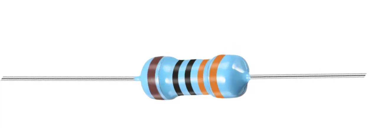
- One resistor for the LED, anywhere from 200 Ω to 1000 Ω.
- One momentary push button switch.
- A breadboard and some DuPont jumper wires.

If you are wondering why a resistor is needed at all, the transcript walks through the math (in video at 03:49). A typical LED drops roughly 2 V across itself and wants about 10 mA of current. With a 5 V supply, the remaining 3 V has to be dropped by the resistor, so Ohm's law gives R = 3 V / 0.01 A = 300 Ω. Anything from 300 Ω up to about 1000 Ω will work — the higher the value, the dimmer the LED, but the safer and more efficient it is. The current is not critical; you simply trade brightness for lower current draw.
Wiring Guide


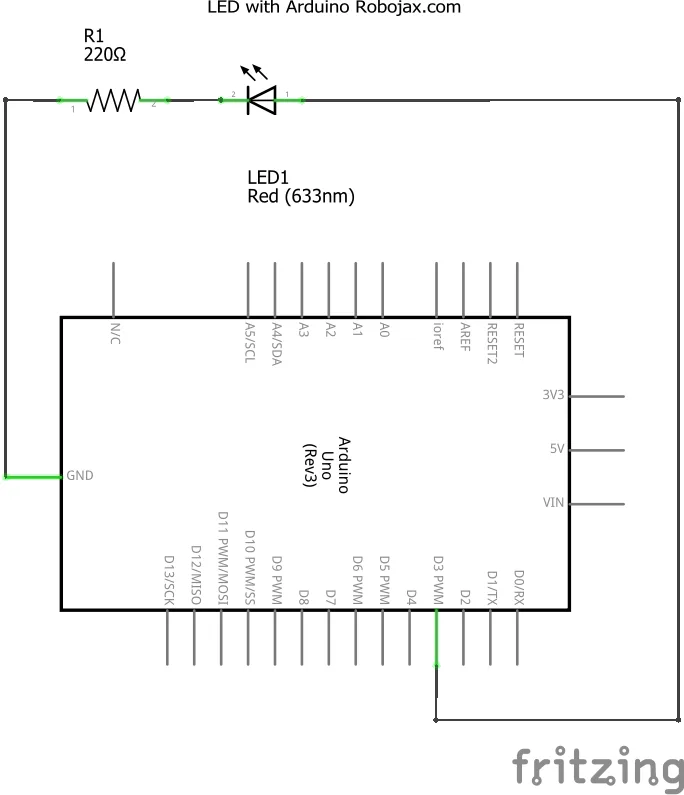
The circuit is the same LED circuit you would use for a blink sketch, with a push button added. The LED's anode (the longer leg) connects through the resistor to Arduino pin 3, and the cathode (the shorter leg, marked by the flat side of the plastic rim) goes to ground. The push button connects between pin 2 and ground.
One detail worth knowing: the push button has four legs, but they are internally paired. Two of the legs are permanently connected to each other, and the other two are permanently connected to each other — pressing the button bridges the two pairs. If you have a multimeter, use its continuity (beep) mode to find which legs are already connected when the button is not pressed; those two are the pair you should not use. Pick one leg from each of the two independent pairs (in video at 07:50).
How the Code Works
The sketch is short, and almost all of it is configuration you can adjust. The three lines at the top are the ones you will actually touch:
const int pushButtonPin = 2;//define a pin number for push button
const int LEDPin = 3;//define a pin that is connected to LED
const int delayLED = 0;//how long the LED should stay ON
pushButtonPin is the digital pin the button is wired to. Change this if you move the button to a different pin — just remember to move the physical wire to match.
LEDPin is the pin driving the LED. Any digital pin will do, but keep in mind that pins 0 and 1 are used by the serial connection, so it is best to avoid them.
delayLED is the most interesting setting. It controls how long the LED stays on after you release the button, measured in milliseconds. Setting it to 0 means the LED turns off the instant you lift your finger. Setting it to 1000 keeps the LED lit for one full second after release, and 5000 keeps it on for five seconds (in video at 16:31). This single number completely changes how the project feels, and it is a good way to see how a variable in code translates directly into behavior you can observe.
Two other things in the setup are worth noting. First, the button pin is configured with INPUT_PULLUP rather than plain INPUT:
pinMode(pushButtonPin, INPUT_PULLUP);//define a pin for push button switch
This enables the Arduino's internal pull-up resistor, which holds the pin at a stable HIGH level when the button is not pressed. Without it, a floating input pin would pick up stray electrical noise and give random readings, and you would need an external resistor to fix it. With the internal pull-up enabled, the wiring stays simple: one side of the button to the pin, the other side to ground. When you press the button, the pin is pulled down to ground and reads LOW (in video at 14:08).
Second, the serial monitor is started at 9600 baud so you can watch the state changes as they happen:
Serial.begin(9600);//initialize the serial monitor
Serial.println("Robojax LED with push button");//print this text on Serial Monitor
In the main loop, the logic is a simple if/else. The code reads the button pin and compares it against LOW. If the button is pressed, the LED pin goes HIGH, the message "LED ON" is printed, and the sketch waits for delayLED milliseconds. If the button is not pressed, the LED pin goes LOW and the LED turns off. Because loop() runs over and over, this check happens thousands of times per second, so the response feels instant.
Live Demonstration
With delayLED set to 1000, pressing the button lights the LED and it stays on for a second after you release it. Drop the value to 5000 and the LED lingers for five seconds — long enough that you can walk away from the button and still see it on. Set it to 0 and the LED follows your finger exactly: press, on; release, off (in video at 17:02).
Once the code is uploaded, you can disconnect the Arduino from USB and power it from a battery or a 5 V adapter. The board does not need a computer to run — the program is stored in its memory and starts automatically every time it is powered on (in video at 12:27).
If you would rather have the LED stay on after a single press and turn off on the next press, that is a different behavior called toggling, and it is covered in Lesson 98-3: How to Turn On/Off a Toggle LED Using a Push Button with Arduino. The push button wiring is identical, so you can reuse this exact circuit.
Related projects from this video
- Lesson 98-1: How to Turn On and Off an LED with Arduino
- Lesson 98-3: How to Turn On/Off a Toggle LED Using a Push Button with Arduino
- Lesson 98-4: Fading an LED Light Using Arduino: Brightness Control
- Lesson 98-5: Fade Light When a Button Is Pressed Using Arduino
- Lesson 98-6: Seesaw LED Game with Arduino
- Lesson 98-7: Walking Light Using Arduino and 5 LEDs
- Lesson 98-8: Walking Light with Push Button and LEDs with Arduino
- Lesson 98-9: LED Voltage Level Meter Using Arduino or walking light with potentiometer
- Lesson 98-10: Arduino Traffic Light
Chapters
- [00:00] Overview of the 10 projects in this video
- [01:00] Introduction to the Arduino step-by-step course
- [02:29] What an LED is: symbol, anode, cathode, and physical shape
- [03:49] Calculating the LED resistor with Ohm's law
- [07:32] Wiring the LED and push button on the breadboard
- [08:50] Explaining the code: pins, setup, and the main loop
- [12:43] How a push button switch works
- [13:22] Wiring the push button to pin 2 and ground
- [13:43] Code walkthrough: INPUT_PULLUP and reading the button
- [16:14] Demonstration: changing delayLED from 1 s to 5 s to 0
- [19:52] Practical applications of a push button toggle
Images




This code has not been parsed yet. Please return to the admin panel to parse it.Things you might need
-
AmazonSunFounder Arduino Learning Kit on AliExpresss.click.aliexpress.com
-
Amazon
-
Amazon
-
Amazon
Resources & references
-
DocumentationDocumentation for SunFounder 3 in 1 IoT/Smart Car/Learning Kitdocs.sunfounder.com
-
External
-
External
-
External
Files📁
Arduino Libraries (zip)
-
SunFounder's 3-in-1 Smart Car learning kit source code
3in1-kit-main-v2.zip12.80 MB
User’s Manual
-
SunFounder 3-in-1 Arduino Smart Car assembly manualThis document shows step by step assembly of SunFounder 3-in-1 Arduino Smart Car
SunFounder_car_assembly_manual.pdf1.20 MB