Lesson 98-7: Walking Light Using Arduino and 5 LEDs
A walking light (also called a "chasing" or "Knight Rider" light) is one of the classic beginner Arduino projects — and for good reason. It teaches you how to control multiple outputs in sequence, how to time events, and how to think about current-limiting resistors, all while producing something visually satisfying. In this project you will wire five LEDs to an Arduino and program them so that each one lights up in turn, creating the illusion of a single light "walking" along the row.
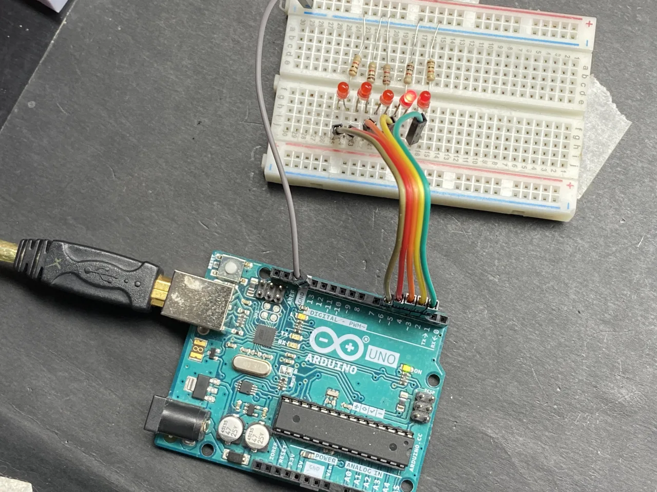
Once you understand the pattern, you can repurpose it in a surprising number of real-world builds:
- Decorative lighting: a chasing border for a shelf, picture frame, or model.
- Direction indicators: a sequential turn-signal effect for a prop vehicle or e-bike.
- Progress or status display: a row of LEDs that advances as a process completes.
- Game and scoreboard props: a "moving target" or level indicator.
- Teaching aid: the clearest possible demonstration of digital outputs and timing.
The same five-LED wiring is reused in several other projects in this course, so the hardware you build here becomes a reusable platform.
How the Walking Light Works
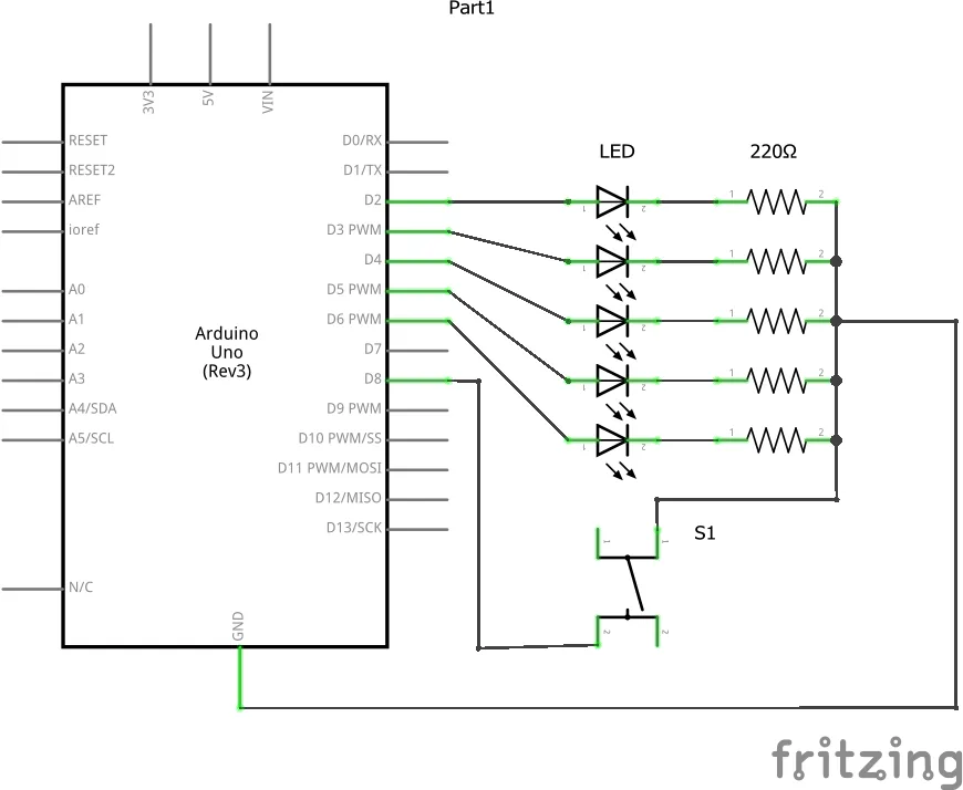
The principle is exactly the same as turning on a single LED — it is simply repeated five times (in video at 30:47). Each LED is connected to its own Arduino pin through its own current-limiting resistor, and all the resistors share a common ground rail. The sketch then turns one pin HIGH, waits, turns it LOW, waits, and moves on to the next pin. Because only one LED is ever on at a time, the eye reads the sequence as motion.
The two timing values are what give the effect its character. The on time controls how long each LED stays lit, and the off time controls the gap before the next LED lights. A short on time with a long off time produces a single dot travelling quickly; a long on time with a short off time produces a smoother, more continuous sweep (in video at 35:00).
Hardware and Components
- 1 × Arduino board (Uno, Nano, or similar)
- 5 × LEDs (any colour; mixing colours makes the effect easier to read)
- 5 × resistors — 300 Ω to 1 kΩ work well
- 1 × breadboard
- Jumper wires
- USB cable or battery pack for power
If you want to add a push-button variant later, you will also need one momentary push button and two extra jumper wires.
Choosing the Resistor Value
An LED has a forward voltage of roughly 2 V and wants about 10 mA for full brightness (in video at 03:49). With a 5 V supply, the resistor must drop the remaining 3 V. Applying Ohm's law, R = V / I = 3 V / 0.01 A = 300 Ω. In practice anything from 300 Ω up to about 1 kΩ will work — the higher the resistance, the dimmer the LED, but the safer and more efficient the circuit (in video at 05:33).
Wiring Guide
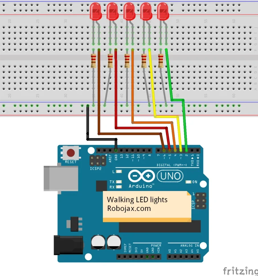
Insert the five LEDs into the breadboard with their anodes (the longer leg) facing the same direction. Connect each cathode (the shorter, flat-sided leg) to its own resistor, and join the far end of all five resistors to a common ground rail. Then run a jumper from each anode to an Arduino pin.
In this build the LEDs are assigned to pins 3, 4, 5, 6 and 7 (in video at 31:29). The pin numbers are defined at the top of the sketch, so if you prefer a different arrangement you only need to change those five lines.
Code Explanation
The sketch is deliberately simple so that a beginner can follow every line. Only the block at the very top needs to be edited for your own setup.
const int LED1 = 3;
const int LED2 = 4;
const int LED3 = 5;
const int LED4 = 6;
const int LED5 = 7;
int offTime = 30;  // the time each LED waits in the OFF state
int onTime = 100;  // the time each LED is ON
Pin definitions. The five const int lines map each LED to a physical Arduino pin. Because they are declared const, the values cannot be changed later in the program — this is a safety habit that prevents accidental reassignment. If you wire your LEDs to different pins, change the numbers here and nothing else.
onTime and offTime. These two integers are the only "behaviour" variables in the project, and they are the ones you will want to experiment with:
onTime— how long (in milliseconds) each LED stays lit. Larger values make each step feel slower and more deliberate.offTime— the pause after an LED turns off before the next one lights. Smaller values make the light travel faster.
Try onTime = 200 and offTime = 200 for an even, medium-speed chase, or onTime = 30 and offTime = 30 for a very fast, almost blurred effect (in video at 36:06).
The setup() function runs once and simply sets all five pins to OUTPUT mode. The loop() function then repeats the same four-step pattern for each LED: drive the pin HIGH, wait onTime, drive it LOW, wait offTime. When the fifth LED finishes, the loop restarts from the first, producing an endless walk.
Live Project and Demonstration
With the default values the LEDs step along the row at a relaxed pace. Uploading the sketch with onTime and offTime set to 200 ms gives a steady, even march; dropping both to 30 ms makes the light streak across the row almost too fast to follow (in video at 36:21).
Two useful experiments to try once it works:
- Make the on time shorter than the off time to create a distinct travelling dot.
- Make the on time longer than the off time to create a soft, overlapping glow.
The same five-LED wiring is reused in the next project, where a push button advances the light one step at a time. That build is covered in Lesson 98-8: Walking Light with Push Button and LEDs with Arduino.
If you would rather drive the row from an analogue input instead of a button, see Lesson 98-9: LED Voltage Level Meter Using Arduino or walking light with potentiometer.
Taking It Further
Once the basic walk works, a natural next step is to make the light bounce back and forth instead of jumping from the last LED to the first. That is a pure code exercise — no extra hardware — and it is a good way to practise loops and arrays. You can also combine this project with the push-button version to build a manually advanced display.
Related projects from this video
- Lesson 98-1: How to Turn On and Off an LED with Arduino
- Lesson 98-2: How to Turn On and Off an LED Using a Push Button with Arduino
- Lesson 98-3: How to Turn On/Off a Toggle LED Using a Push Button with Arduino
- Lesson 98-4: Fading an LED Light Using Arduino: Brightness Control
- Lesson 98-5: Fade Light When a Button Is Pressed Using Arduino
- Lesson 98-6: Seesaw LED Game with Arduino
- Lesson 98-8: Walking Light with Push Button and LEDs with Arduino
- Lesson 98-9: LED Voltage Level Meter Using Arduino or walking light with potentiometer
- Lesson 98-10: Arduino Traffic Light
Chapters
- [00:00] Overview of the ten LED projects
- [01:22] Introduction to the Arduino step-by-step course
- [02:29] What an LED is and how to identify its pins
- [03:49] Calculating the current-limiting resistor
- [30:47] Introducing the walking light project
- [31:06] Wiring diagram for five LEDs
- [32:52] Walking light code walkthrough
- [34:39] Demonstration and changing the timing values
- [36:41] Advancing the light with a push button (separate tutorial)
- [42:25] LED voltage bar with potentiometer (separate tutorial)
- [49:25] Arduino traffic light (separate tutorial)
Images

This code has not been parsed yet. Please return to the admin panel to parse it.Things you might need
-
AmazonSunFounder Arduino Learning Kit on AliExpresss.click.aliexpress.com
-
Amazon
-
Amazon
-
Amazon
Resources & references
-
DocumentationDocumentation for SunFounder 3 in 1 IoT/Smart Car/Learning Kitdocs.sunfounder.com
-
External
-
External
-
External
Files📁
Arduino Libraries (zip)
-
SunFounder's 3-in-1 Smart Car learning kit source code
3in1-kit-main-v2.zip12.80 MB
User’s Manual
-
SunFounder 3-in-1 Arduino Smart Car assembly manualThis document shows step by step assembly of SunFounder 3-in-1 Arduino Smart Car
SunFounder_car_assembly_manual.pdf1.20 MB