Lesson 98-6: See saw LED Game with Arduino
The seesaw LED project is a classic beginner exercise that teaches one of the most important concepts in Arduino programming: making two outputs alternate in a timed rhythm. Using just two LEDs, two resistors, and a handful of jumper wires, you'll build a circuit where a green LED and a red LED take turns lighting up, mimicking the up-and-down motion of a playground seesaw. It's a simple build, but it introduces the core building blocks — pin definitions, timing constants, and sequential digitalWrite() calls — that appear in almost every Arduino sketch you'll ever write.
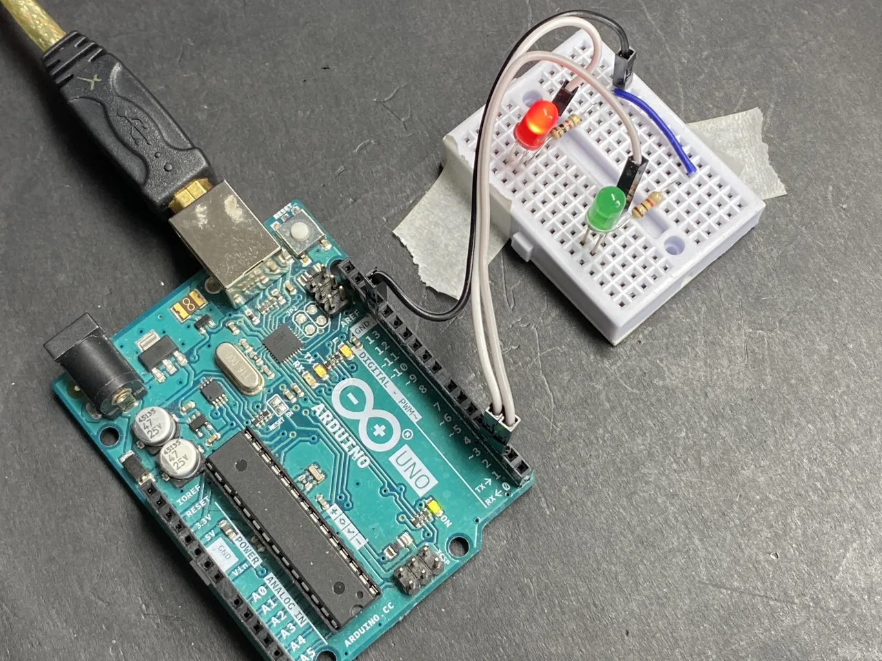
Because the seesaw pattern is really just "turn one thing on, turn it off, turn the other thing on, turn it off, repeat," the same structure scales into dozens of practical uses. Here are a few ideas to spark your imagination:
- Alternating indicator lights — a "safe / alert" pair on a control panel that swaps back and forth.
- Railroad crossing simulation — two lamps blinking in alternation as a train approaches.
- Two-lane direction sign — a "go this way / go that way" arrow display for a driveway or parking lot.
- Holiday decoration — red and green LEDs trading places for a festive blinking effect.
- Learning foundation — the timing and sequencing skills here are the same ones you'll later use for traffic lights, walking lights, and multi-LED animations.
How the Seesaw Effect Works
An LED is a diode that emits light, and its symbol is a triangle pointing at a line. The flat line is the cathode (negative), and the back of the triangle is the anode (positive). On a physical LED, the longer leg is the anode and the shorter, flat-sided leg is the cathode. Current flows from anode to cathode, so the anode connects toward your Arduino pin and the cathode connects through a resistor to ground (in video at 02:29).
The resistor matters. A typical small LED wants roughly 2 V across it and about 10 mA of current. If your Arduino supplies 5 V, the remaining 3 V must be dropped by the resistor. Using Ohm's law, R = V / I = 3 V / 0.01 A = 300 Ω. Anything from about 300 Ω up to 1000 Ω will work — higher values simply make the LED dimmer (in video at 03:49).
For the seesaw, the two LEDs are wired identically: each anode goes to its own Arduino pin, and each cathode goes through its own resistor to a shared ground rail. The only difference between the two is which pin they're attached to.
Hardware and Components
- 1 × Arduino board (Uno, Nano, Mega, or similar)
- 2 × LEDs — one red, one green (any two colors work)
- 2 × resistors, 300 Ω to 1000 Ω (220 Ω or 330 Ω are common choices)
- 1 × breadboard
- Jumper wires (DuPont wires)
- USB cable for programming and power
That's it — no push buttons, no potentiometers, no sensors. This is deliberately the leanest possible parts list so you can focus entirely on the code logic.
Wiring Guide


The wiring is symmetrical and easy to follow. Insert both LEDs into the breadboard. Connect the anode (longer leg) of the green LED to Arduino pin 2 and the anode of the red LED to Arduino pin 3. Each cathode (shorter leg) connects to one end of its own resistor, and the other end of both resistors joins a common rail that runs to the Arduino's GND pin (in video at 27:45).
Because both LEDs share the same ground rail, only one ground wire is needed from the breadboard back to the Arduino. The two signal wires — one to pin 2, one to pin 3 — are the only connections that change between the two LEDs.
Code Explanation
The sketch is intentionally short so every line is meaningful. Here are the parts you'll actually want to adjust:
Pin Definitions
const int greenLEDPin = 2;//define a pin for green LED
const int redLEDPin = 3;//define a pin for red LED
These two constants tell the Arduino which pins the LEDs are connected to. If you wired your LEDs to different pins — say pin 8 and pin 9 — this is the only place you need to change. The const keyword means the value is fixed for the lifetime of the program and cannot be accidentally overwritten later.
Timing Constant
const int ON_TIME = 500;This single value controls how long each LED stays lit, in milliseconds. The default of 500 means each LED is on for half a second, so a full green-then-red cycle takes one second. Lower it to 200 for a fast blink, or raise it to 1000 for a slow, deliberate one-second-per-LED rhythm (in video at 30:17). Because both LEDs share this constant, they always stay in sync — the seesaw stays balanced.
Setup
Inside setup(), the two pins are declared as outputs with pinMode(), and the serial monitor is started at 9600 baud so you can watch the LED state messages scroll by. This runs once, when the board powers up.
The Loop
The loop() function is where the seesaw happens. It performs four actions in sequence: turn the green LED on, wait ON_TIME milliseconds, turn it off, then do the same for the red LED. When the loop reaches the end, it starts over from the top automatically — that's the entire "seesaw" behavior. There's no state variable and no condition to check, because the pattern is purely sequential.
Live Project and Demonstration
Once the code is uploaded, you'll see the green LED light for half a second, then the red LED, then green again, endlessly. Opening the serial monitor (Tools → Serial Monitor, or Ctrl+Shift+M) shows "Green LED ON" and "Red LED ON" printed as the pattern runs, which is a handy way to confirm the timing matches what you set.
Try changing ON_TIME to 200 and re-uploading — the LEDs will swap noticeably faster. Set it to 1000 and the seesaw becomes a slow, deliberate alternation. You can also disconnect the Arduino from USB and power it from a battery or a 5 V adapter; the sketch runs identically because it's already stored in the board's memory.
Related projects from this video
- Lesson 98-1: How to Turn On and Off an LED with Arduino
- Lesson 98-2: How to Turn On and Off an LED Using a Push Button with Arduino
- Lesson 98-3: How to Turn On/Off a Toggle LED Using a Push Button with Arduino
- Lesson 98-4: Fading an LED Light Using Arduino: Brightness Control
- Lesson 98-5: Fade Light When a Button Is Pressed Using Arduino
- Lesson 98-7: Walking Light Using Arduino and 5 LEDs
- Lesson 98-8: Walking Light with Push Button and LEDs with Arduino
- Lesson 98-9: LED Voltage Level Meter Using Arduino or walking light with potentiometer
- Lesson 98-10: Arduino Traffic Light
Chapters
- [00:00] Overview of the 10 Arduino LED projects
- [01:22] Introduction to the Arduino step-by-step course
- [02:29] Understanding LEDs: symbol, anode, and cathode
- [03:49] Calculating the LED series resistor with Ohm's law
- [27:32] Introducing the seesaw LED project
- [27:45] Wiring diagram for the seesaw project
- [28:28] Explaining the seesaw code
- [30:06] Demonstrating the seesaw with different timings
- [30:47] Walking light project overview
- [36:41] Walking light controlled by push button
- [42:25] LED voltage bar meter with potentiometer
- [49:25] Arduino traffic light project
ภาพ
This code has not been parsed yet. Please return to the admin panel to parse it.สิ่งที่คุณอาจต้องการ
-
อเมซอนSunFounder Arduino Learning Kit on AliExpresss.click.aliexpress.com
-
อเมซอน
-
อเมซอน
-
อเมซอน
แหล่งข้อมูลและเอกสารอ้างอิง
-
เอกสารDocumentation for SunFounder 3 in 1 IoT/Smart Car/Learning Kitdocs.sunfounder.com
-
ภายนอก
-
ภายนอก
-
ภายนอก
ไฟล์📁
ไลบรารี Arduino (zip)
-
SunFounder's 3-in-1 Smart Car learning kit source code
3in1-kit-main-v2.zip12.80 MB
คู่มือผู้ใช้
-
คู่มือการประกอบรถอัจฉริยะ SunFounder 3-in-1 Arduino Smart Carเอกสารนี้แสดงการประกอบ SunFounder 3-in-1 Arduino Smart Car ทีละขั้นตอน
SunFounder_car_assembly_manual.pdf1.20 MB