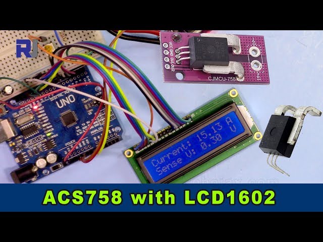
اندازهگیری جریان با استفاده از حساس(حس کننده) جریان Allegro ACS758 و LCD1602 برای آردوینو
این پروژه نشان میدهد چگونه میتوان جریان را با استفاده از حساس(حس کننده) جریان Allegro ACS758 اندازهگیری کرد و قرائتها را روی صفحه LCD1602 متصل به یک آردوینو نمایش داد. ACS758 یک حساس(حس کننده) چندمنظوره است که قادر به اندازهگیری جریان تا 200 آمپر میباشد و آن را برای کاربردهای مختلف مناسب میسازد.

این پروژه روش عملیای برای نظارت بر جریان در یک مدار فراهم میکند که برای کاربردهای مختلف از جمله موارد زیر حیاتی است:
- پایش مصرف برق در دستگاهها
- ساخت یک سیستم مدیریت باتری
- طراحی کنترلکنندهٔ موتور الکتریکی
- ایجاد یک سیستم امنیتی مبتنی بر جریان
این راهنما شما را مرحلهبهمرحله در مورد سختافزار لازم، سیمکشی، شِفر (کود) و یک نمایش زنده راهنمایی خواهد کرد.
پایههای سختافزاری

سختافزار/قطعات
برای ساخت این پروژه به قطعات زیر نیاز خواهید داشت:
- آردوینو اونو (یا سازگار)
- حساس(حس کننده) جریان Allegro ACS758 (شماره مدل دقیق تعیینکننده حداکثر مقدار جریان قابل اندازهگیری است؛ مطمئن شوید شِفر (کود) را متناسب تنظیم کنید. (در ویدئو در 00:14 و 03:18))
- نمایشگر LCD1602 بدون ماجیول I2C،السیدی 12 سیم دارد.
- سیمهای اتصال
- منبع تغذیه (5V)
- بار (برای آزمایش اندازهگیری جریان)

راهنمای سیمکشی
")
سیمکشی LCD1602 در یک ویدئوی جداگانه توضیح داده شده است (در ویدئو در 01:24). اتصالات کلیدی برای این پروژه بهصورت زیر است (در ویدئو در 01:24):
- ACS758: VCC به 5V، GND به GND، خروجی سیگنال (سیم زرد) به A0 روی آردوینو.
- دو سیم اصلی حساس(حس کننده) ACS758 به صورت سری با بار متصل شدهاند (در ویدئو در 02:09).
توضیح شِفر (کود)
شِفر (کود) آردوینو از دو بخش اصلی تشکیل شده است: یکی برای کار با حساس(حس کننده) ACS758 و دیگری برای تعامل با LCD1602. بخشهای قابل تنظیم توسط کاربر در شِفر (کود) عبارتند از:
#define VIN A0 // define the Arduino pin A0 as voltage input (V in)
const float VCC   = 5.0;// supply voltage 5V or 3.3V. If using PCB, set to 5V only.
const int model = 2;   // enter the model (see below)
float cutOffLimit = 1.00;// reading cutoff current. 1.00 is 1 Amper
آنmodelمتغیر باید مطابق با مدل خاص ACS758 مورد استفاده تنظیم شود (در ویدیو در 03:18). به کامنتهای شِفر (کود) برای نگاشت شماره مدل مراجعه کنید. اینcutOffLimitمتغیر حداقل جریان قابل نمایش را تعیین میکند (در ویدئو در 03:48). این مقدار را تنظیم کنید تا خوانشهای ناچیز فیلتر شوند.
پروژه/نمایش زنده
ویدیو نشان میدهد چگونه آمپرمتر را برای اندازهگیری جریانی که از بار عبور میکند متصل کنیم (در ویدیو در 02:18). شِفر (کود) مقادیر جریان و ولتاژ را روی هر دو LCD1602 و نمایشگر مسلسل نمایش میدهد (در ویدیو در 07:02). نمایش نشان میدهد که خوانشها بهصورت پویا هنگام تغییر جریان بار بهروز میشوند (در ویدیو در 07:14). همچنین نشان میدهد که وقتی جریان زیر حد مشخص میافتد، «No Current» نمایش داده میشود (در ویدیو در 07:59).
فصلها
- [00:06] مقدمه
- [00:34] پیشنیازها
- [01:24] توضیح سیمکشی
- [02:18] نمایش اندازهگیری جریان
- [02:57] توضیح شِفر (کود)
- [07:02] نمایش زنده
- [08:18] نتیجهگیری
تصاویر
This code has not been parsed yet. Please return to the admin panel to parse it.مواردی که ممکن است به آنها نیاز داشته باشید
-
علیاکسپرسخرید حساس(حس کننده) جریان Allegro ACS758 از علیاکسپرسs.click.aliexpress.com
منابع و مراجع
فایلها📁
هیچ فایلی موجود نیست.