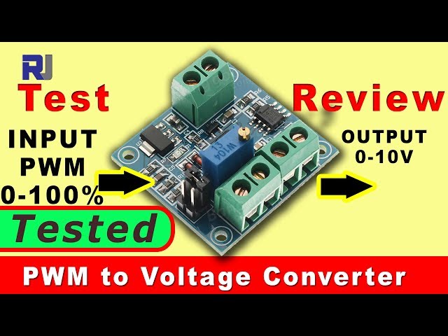
Convert PWM to Voltage using IC Station converter (Review and Test )
This project guide provides a comprehensive review and test of the IC Station PWM to voltage converter module. This module is invaluable for various applications where precise control of voltage based on PWM signals is needed. Practical uses include:
- Motor speed control
- Precisely controlling LED brightness
- Creating a custom power supply with adjustable output
- Building a signal processing circuit
- Educational projects demonstrating PWM to voltage conversion
This guide will walk you through the module's features, wiring, and testing procedures, enabling you to effectively utilize this versatile component in your projects.
Hardware/Components
The core of this project is the IC Station PWM to voltage converter module (in video at 00:12). The module accepts a PWM signal as input (0-100% duty cycle) and outputs a corresponding 0-10V voltage. It features a 12V voltage regulator (in video at 01:17), allowing for input voltages ranging from 12V to 30V. A potentiometer (in video at 01:30) allows for adjustment of the output voltage range. A crucial safety feature is the inclusion of a PC817 sharp photocoupler (in video at 01:49) for electrical isolation. Jumpers allow selection of the input voltage range (4.5-12V or 12-24V) (in video at 01:41). An LM358 dual operational amplifier is used in the circuit (in video at 02:44).
Wiring Guide
The video demonstrates the wiring setup (in video at 04:01). The module's 12V input is connected to a power supply. The PWM signal is provided by a function generator, and the output voltage is measured using a multimeter.
%%WIRING%%
Live Project/Demonstration
The video demonstrates the functionality of the PWM to voltage converter (in video at 04:14). The function generator is used to input PWM signals with varying duty cycles. The output voltage is monitored using a multimeter and is shown to closely correspond to the duty cycle percentage. The video highlights the linearity of the conversion up to approximately 85% duty cycle (in video at 14:03). A calibration procedure is demonstrated, emphasizing the importance of adjusting the potentiometer (in video at 06:31) to match the input signal voltage. The minimum input voltage required for stable operation is also determined experimentally (in video at 10:43) to be around 14V.
The video also shows the effects of adjusting the input voltage range using the jumpers (in video at 08:02) and how this impacts the output voltage. Finally, the maximum achievable output voltage is shown to be approximately 10.12V (in video at 12:44) when the input voltage is properly regulated.
Chapters
- [00:05] Introduction and Overview
- [00:53] Module Features and Specifications
- [01:55] Circuit Diagram and Explanation
- [03:07] Product Page and Specifications
- [04:01] Wiring and Setup
- [04:14] Live Demonstration and Testing
- [13:57] Data Analysis and Linearity
- [16:10] Conclusion
Things you might need
-
eBay
-
AliExpressPurchase PWM to voltage module for Arduino from AliExpresss.click.aliexpress.com
-
AliExpressPurchase PWM to voltage module from AliExpress (1)s.click.aliexpress.com
Resources & references
No resources yet.
Files📁
No files available.