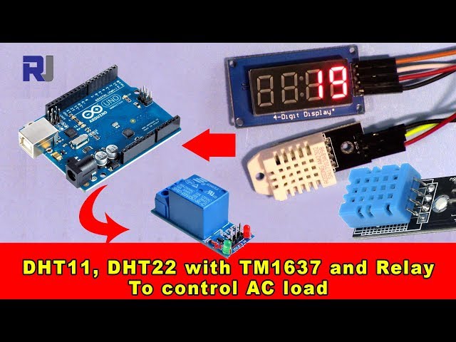
Using DHT11, DHT22 with TM1637 display and Relay to control AC load
This project demonstrates how to build a temperature-controlled system using an Arduino, DHT11/DHT22 temperature and humidity sensor, a TM1637 display, and a relay to control an AC load. This setup is incredibly versatile and can be adapted for various applications. For example, you could build:
- A smart thermostat for a small greenhouse, automatically adjusting a heater or fan based on temperature readings.
- A system to monitor and control the temperature of a liquid in a chemical process.
- An automated temperature control system for a reptile enclosure.
- A temperature-activated alarm system, triggering an alert when a certain threshold is reached.
The system uses a DHT11 or DHT22 sensor to measure temperature and humidity (in video at 00:11). The TM1637 display shows the current temperature (in video at 00:17), and a relay switches an AC load (like a light, fan, or heater) on or off based on pre-defined temperature settings (in video at 00:23).
Hardware/Components
To build this project, you will need the following components:
- Arduino Uno (or compatible board)
- DHT11 or DHT22 Temperature and Humidity Sensor (in video at 00:11)
- TM1637 Display Module (in video at 00:17)
- Relay Module (in video at 00:19)
- Jumper Wires
- Breadboard
- AC Load (e.g., a small light bulb or fan)
Wiring Guide
The wiring is straightforward but crucial for the project's functionality. Refer to the video for a visual guide.
%%WIRING%%
Detailed wiring instructions and diagrams can be found in the video (in video at 02:03 to 05:18). Pay close attention to the connections for the DHT sensor (in video at 01:44), TM1637 display (in video at 02:25), and relay module (in video at 03:37).
Code Explanation
The Arduino code uses two libraries: TM1637Display and DHT sensor library. You'll need to install these libraries in the Arduino IDE. The most important configurable parts of the code are:
// Module connection pins (Digital Pins)
#define CLK 2
#define DIO 3
// The amount of time (in milliseconds) between tests
#define TEST_DELAY   1000
// ****** end of TM1637 Display code

#define DHTPIN 9     // what digital pin we're connected to
#define DHTTYPE DHT22   // DHT 22  (AM2302), AM2321
#define RELAY 7 // the pin connected to relay
The #define statements allow you to easily change the pin assignments for the TM1637 display (CLK and DIO), DHT sensor (DHTPIN), and relay (RELAY) to match your wiring. The DHTTYPE defines which DHT sensor you are using (DHT11 or DHT22). The TEST_DELAY variable controls the time between readings.
The getTemp() function is a custom function used to read temperature and humidity data from the DHT sensor. It allows you to request different data types (Celsius, Fahrenheit, humidity, heat index) by passing a string argument (in video at 09:01 to 10:34). For example: getTemp("c") returns the temperature in Celsius, and getTemp("h") returns the humidity.
if(temp >50 )
 {
  digitalWrite(RELAY, LOW);
 }else{
  digitalWrite(RELAY, HIGH);
 }
This code section controls the relay based on the temperature. Modify the threshold value (50 in this example) to adjust the trigger point (in video at 09:44 to 10:11).
Live Project/Demonstration
A full demonstration of the project is available in the video (in video at 00:51 to 01:07). The video shows the system in action, displaying the temperature on the TM1637 display and controlling the AC load based on the temperature readings.
Chapters
- [00:06] Introduction and Project Overview
- [01:12] Code Availability and Additional Resources
- [01:44] DHT Sensor Wiring
- [02:25] TM1637 Display Wiring
- [02:50] AC Load and Relay Wiring
- [04:33] Relay Pin and Power Connections
- [05:29] Library Installation
- [05:52] Code Explanation: TM1637 Section
- [06:47] Code Explanation: DHT Section
- [07:50] Code Explanation: Relay and Setup
- [08:26] Code Explanation: Loop and Temperature Control
- [10:12] getTemp() Function Explanation
This code has not been parsed yet. Please return to the admin panel to parse it.منابع و مراجع
هنوز هیچ منبعی موجود نیست.
فایلها📁
هیچ فایلی موجود نیست.