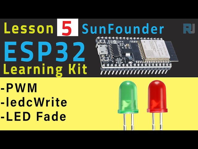
ESP32 チュートリアル 5/55 - LED フェード、LED の明るさを制御 - ESP32 IoT 学習キット
このチュートリアルでは、ESP32マイクロコントローラー、具体的にはSunFounder ESP32 IoT Learning Kitを使用して、LEDの明るさを制御する方法を示します(動画の00:04)。このプロジェクトは、パルス幅変調(PWM)と光源の強度制御に関するアプリケーションを学んでいる初心者に最適です。ESP32の内蔵PWM機能により、スムーズで精密な制御が可能になり、クリエイティブなプロジェクトの新しい可能性が広がります。
実用的な応用:
- 調光可能なアンビエント照明システムの作成。
- 徐々にフェードアウトするシンプルなナイトライトを作る。
- さまざまな状態(例:バッテリー残量低下、ネットワーク接続)のための動的インジケーターライトを開発する。
- 他のセンサーやアクチュエーターと統合して、複雑なインタラクティブインスタレーションを作成します。
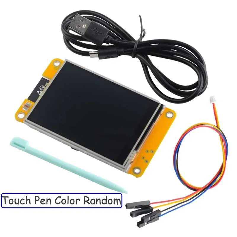
ハードウェア/コンポーネント
このプロジェクトでは、ESP32マイクロコントローラー、拡張ボード、さまざまなコンポーネント、18650リチウムバッテリーを含むSunFounder ESP32スターターキット(動画の00:12で)を使用します。また、LEDと220オームの抵抗器も必要です(動画の04:32で)。
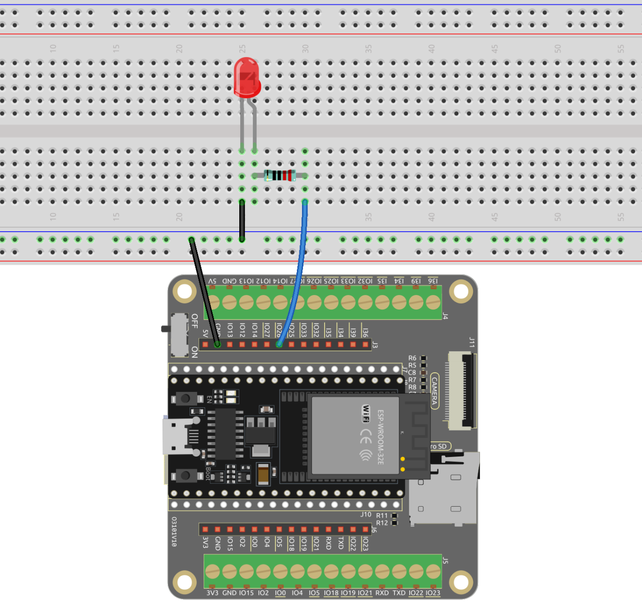
配線ガイド
ビデオの配線図を参照してください(ビデオの01:46と04:18で)およびタイムスタンプ04:40での詳細な説明。配線には、LEDのアノードを抵抗器に接続し、抵抗器をESP32のGPIO 26ピンに接続し、LEDのカソードをグラウンドに接続することが含まれます。
 LEDと抵抗器
220オームの抵抗器と直列に接続されたLED。以下はブレッドボードの配線です。
 LEDフェードESP32
コードの説明
Arduinoコードは、PWM(パルス幅変調)を使用してLEDの明るさを制御します。主な設定可能な部分は次のとおりです:
ledPin: LEDに接続されているGPIOピンを定義します(ビデオの09:41で26に設定されています)。異なるピンを使用する場合はこれを変更してください。fadeAmountLEDの明るさが変わる速さを制御します(動画の10:06で)。値が高いほど、フェードが速くなります。コードは、自動的に明るさが最小(0)または最大(255)値に達したときに方向を逆にします(動画の11:44で)。
const int ledPin = 26;  // The GPIO pin for the LED
int brightness = 0;
int fadeAmount = 5;

void setup() {
  ledcAttachPin(ledPin, 0); // Attach pin to PWM channel
}

void loop() {
  ledcWrite(ledPin, brightness);
  brightness = brightness + fadeAmount;
  if (brightness <= 0 || brightness >= 255) {
    fadeAmount = -fadeAmount;
  }
  delay(50);
}
ライブプロジェクト/デモンストレーション
ビデオでは、消えるLEDの動作を示しています(ビデオの14:51で)。講師は調整方法を示します。fadeAmountフェードの速度を制御するための変数(動画の15:16および15:51で)。ESP32にコードをアップロードするプロセスも示されています(動画の14:20で)。
章
- [00:00] はじめにとプロジェクトの概要
- [00:12] ESP32スターターキットの概要
- [01:46] 配線図と説明
- [02:03] デジタル信号とPWM
- [04:18] LEDの配線
- [06:33] コードの説明: 関数
- [09:11] コードの説明:フェードするLED
- [13:33] コードをアップロード中
- [14:51] ライブデモンストレーションと調整
画像
LED_fade_ESP32
LED_with_Resistor
791-ESP32 Tutorial 5/55 - LED Fade, control brightness of an LED in Arduino
言語: C++
const int ledPin = 26; // LEDのGPIOピン
int brightness = 0;
int fadeAmount = 5;

void setup() {
  ledcAttach(ledPin, 5000, 8); // LEDピンを取り付けてください
}

void loop() {
  ledcWrite(ledPin, brightness); // 新しい明るさの値をPWMピンに書き込む
  brightness = brightness + fadeAmount;
  if (brightness <= 0 || brightness >= 255) {
    fadeAmount = -fadeAmount;
  }
  delay(50); // 50ミリ秒待ってください
}