Using the 28BYJ-48 Stepper Motor with a ULN2003 Driver and Arduino
In this tutorial, we'll guide you through the process of using the popular 28BYJ-48 stepper motor with a ULN2003 motor driver module and an Arduino. Many beginners face challenges when trying to configure these components together. This article will provide a clear explanation of the hardware, wiring, and a step-by-step code walkthrough to get your motor spinning.
This is a fundamental guide focused on getting the motor to rotate clockwise and counter-clockwise. While future tutorials may cover more advanced topics like using sensors to control the motor's speed and direction, this will serve as a solid introduction to get you started.
Specs of the Motor
As detailed around the 01:09 mark in the video, we are using a
5-volt DC stepper motor. A key feature of this motor is its use of four phases, which correspond to the different wire windings inside. The wires are typically colored blue, pink, yellow, and orange, with a red wire that is common to all the windings.
This motor is paired with the
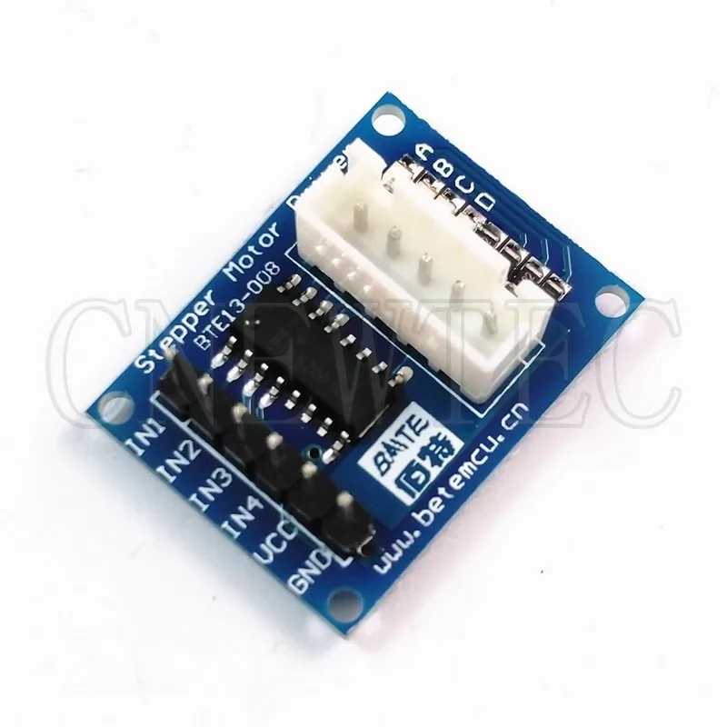
ULN2003 driver board. The ULN2003 chip is essentially an array of amplifiers that takes the low-current signals from the Arduino and boosts them to drive the motor. The ULN2003 version is ideal for this project because it is designed to work with 5V TTL logic, which matches the Arduino's output voltage level perfectly.
Wiring Explained
The wiring for this project is straightforward. You will connect the ULN2003 driver board to your Arduino and to the motor. As shown in the video at 03:20, four input pins on the driver board (IN1, IN2, IN3, and IN4) are used to control the motor's phases. These connect to Arduino pins 10, 11, 12, and 13.
Wiring Diagram Caption:
Here is the wiring diagram for connecting the 28BYJ-48 motor and ULN2003 driver to the Arduino. Note the connections for the motor, the driver inputs, and the separate power supply.
Power Requirement for the Motor
A critical point, as explained at 04:00 in the video, is that the motor requires an external power supply. You should not try to power the motor directly from the Arduino's 5V pin, as it cannot provide enough current. The driver board circuit itself can be powered by the Arduino, but the motor needs its own power source, like a 5V DC power adapter or battery pack.
When you connect your external power source, it's essential to create a common ground. You must
connect the negative (GND) of your external power supply to one of the GND pins on the Arduino. The positive wire from your external supply connects directly to the power input on the ULN2003 driver board.
Code Explained
The Arduino code controls the sequence of signals sent to the driver, which in turn makes the motor move. The full code is available for download below this article. As we walk through the code (explained at 06:09 in the video), you'll see how it works.
First, we define which Arduino pins are connected to the four input pins on the ULN2003 driver. In this case, we use pins 10, 11, 12, and 13.
C++
int Pin1 = 10;
int Pin2 = 11;
int Pin3 = 12;
int Pin4 = 13;
A boolean variable named dir is used to easily control the direction of rotation. Setting it to
true will make the motor turn counter-clockwise, and false will make it turn clockwise.
C++
boolean dir = true;// false=clockwise, true=counter clockwise
In the setup() function, we simply configure these four pins as OUTPUT pins.
C++
void setup()
{
 pinMode(Pin1, OUTPUT);
 pinMode(Pin2, OUTPUT);
 pinMode(Pin3, OUTPUT);
 pinMode(Pin4, OUTPUT);
}
The core of the program is the loop() function. It uses a switch statement that cycles through 8 steps (case 0 to case 7). Each step energizes the motor's coils in a different combination by setting the output pins to HIGH or LOW. This specific sequence of eight steps is what causes the motor shaft to rotate smoothly.
After the switch statement, the code checks the dir variable.
If
diristrue, it increments the_stepvariable (_step++).If
dirisfalse, it decrements it (_step--).
This is how the direction is reversed. The code then ensures the
_step variable always stays between 0 and 7, creating a continuous loop. A small
delay(1) is added to control the speed of the rotation.
Demonstration
Once the code is uploaded to the Arduino and the external power is supplied, the motor will begin to rotate, as seen in the video at 08:00. To change the direction, simply change the dir variable in the code from true to false (or vice-versa), and upload the code again. You will see the motor stop and then begin spinning in the opposite direction.
Video Timestamps
For your convenience, here are the timestamps for the key sections in the video tutorial:
00:00 Introduction
01:09 Specs of the motor
03:20 Wiring Explained
04:00 Power requirement for the motor
06:09 Code Explained
08:00 Demonstration of running motor
Related Links
- Purchase an authentic Arduino UNO R3 from Amazon USA
- Purchase this module from Amazon USA
- Purchase this module from Amazon Canada
- Purchase this module from all other Amazon.
- Purchase PFR120N LR7843 AOD4184 D4184 isolated MOSFET MOS tube FET module replacement relay 100V 9.4A 30V 161A 40V 50A board
- Purchase a 28BYJ-48 stepper motor from Amazon USA
- Purchase a 28BYJ-48 stepper motor from Amazon Canada.
- Purchase a 28BYJ-48 stepper motor from Amazon.
- Purchase 5 pcs 28BYJ-48 stepper motors from AliExpress
- Purchase an authentic Arduino board from Amazon Canada


Comments will be displayed here.