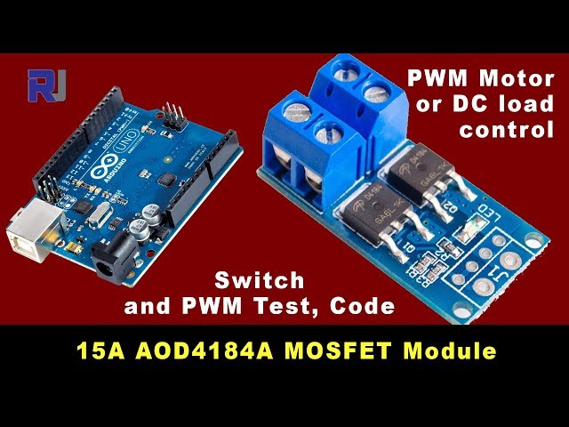
15A 400W MOSFET AOD4184A to Control Motor or Load
This project demonstrates how to use a 15A, 400W MOSFET module (based on the AOD4184A MOSFET) to control various loads, such as motors and lights. This is a valuable skill for numerous applications, allowing precise control over power delivery. The MOSFET's high current capacity makes it suitable for a wide range of projects.
Practical Applications:
- Controlling the speed of DC motors in robotics or automation projects.
- Creating dimming circuits for LED lighting.
- Building a high-power switching circuit for appliances.
- Designing a motor controller for a small vehicle.
Hardware/Components
The core component is a 15A, 400W MOSFET module featuring two AOD4184A MOSFETs in parallel (in video at 00:05). You will also need an Arduino board, a power supply, connecting wires, and the load you wish to control (motor, lights, etc.). A heat sink is highly recommended for higher current applications (in video at 03:40).


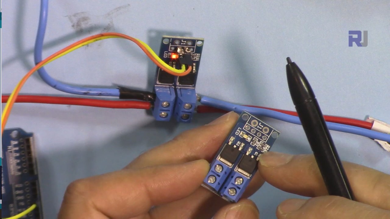
Wiring Guide
The module has clearly marked terminals: input (Vin), output, and ground (in video at 01:42). Connect the positive side of your power supply to the Vin, and the negative to the ground. Your load connects to the output terminals. The Arduino controls the MOSFET module's gate using a digital pin (in video at 08:26).


Code Explanation
The Arduino code uses Pulse Width Modulation (PWM) to control the MOSFET. The configurable parameters are:
motorPin: Specifies the Arduino pin connected to the MOSFET module's gate (default: pin 9). (in video at 05:47)mSpeed: An integer variable controlling the motor speed (0-255). (in video at 05:47)mStep: Determines the increment/decrement step formSpeed(default: 15). Adjust this to fine-tune speed control (in video at 05:54).
int motorPin =9; // pin to connect to motor module
int mSpeed = 0; // variable to hold speed value
int mStep = 15; // increment/decrement step for PWM motor speed
The code includes logic to prevent mSpeed from exceeding the 0-255 range (in video at 07:26). For testing higher currents (5A, 10A, 15A, 20A), a simplified version of the code keeps the output pin HIGH to maintain a constant on state (in video at 13:43).
void loop() {
  digitalWrite(loadPin, HIGH);
  while(1); // wait forever
}
Live Project/Demonstration
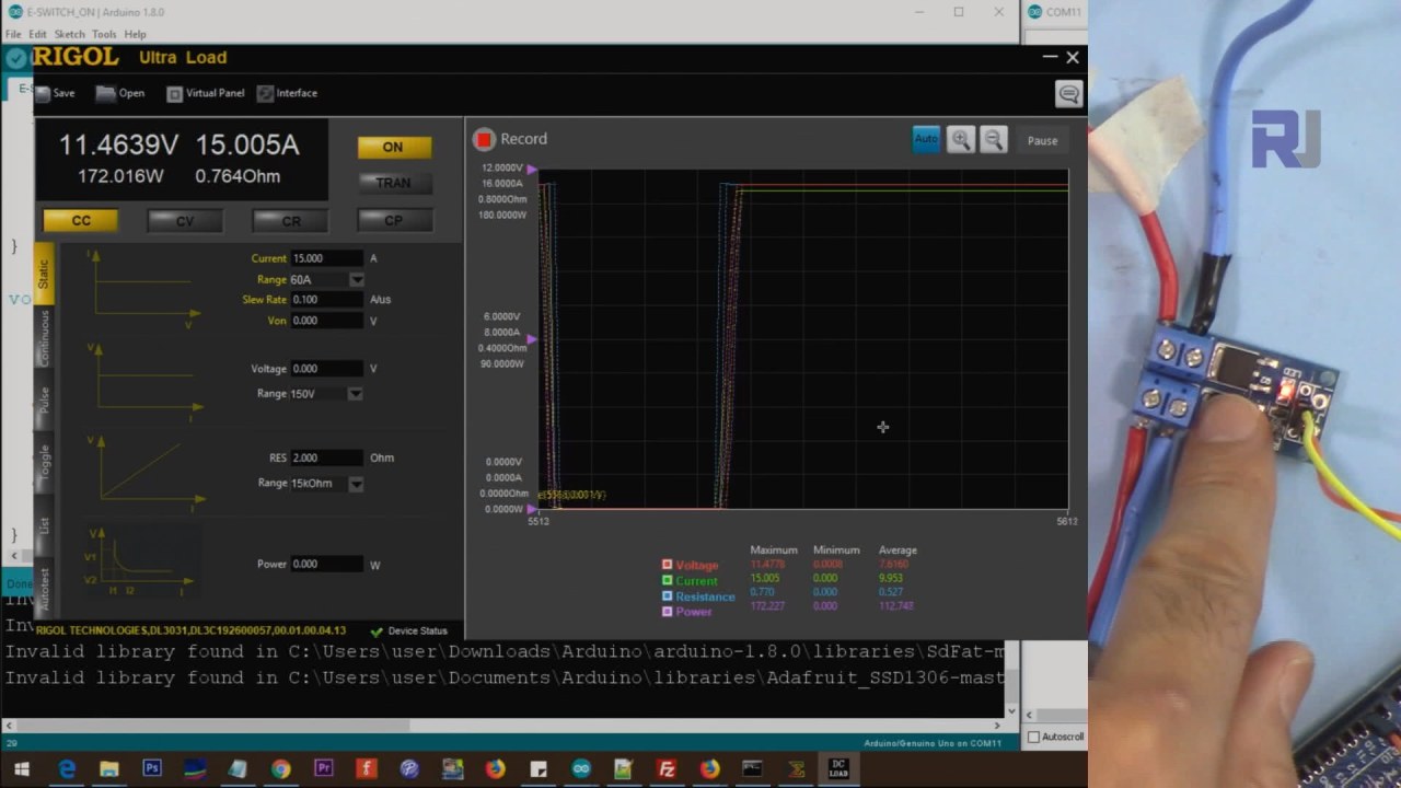
The video demonstrates controlling a 51W light bulb (in video at 10:40) and a DC motor (in video at 11:18) using PWM. The project also includes tests with an electronic load at 5A, 10A, 15A, and 20A (in video at 13:10), showcasing the module's high current handling capabilities. Measurements of the voltage drop across the MOSFET at various currents are also shown (in video at 16:06), validating the low on-resistance of the AOD4184A.
Chapters
- [00:00] Introduction and Project Overview
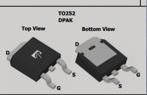
- [01:40] Hardware Overview and Module Details
- [05:01] MOSFET Datasheet Explanation
- [05:47] Code Explanation
- [08:26] Wiring Explanation
- [10:40] Demonstration with 51W Light
- [11:18] Demonstration with DC Motor
- [12:58] High-Current Testing (5A, 10A, 15A, 20A)
- [16:06] Voltage Drop Measurement
Images
/*
 * This is an Arduino sketch for a tutorial video
 * explaining why a resistor is needed when using a push button
 * with an Arduino to connect the pin to Ground (GND)
 *
 * Written by Ahmad Shamshiri on July 18, 2018 at 17:36 in Ajax, Ontario, Canada
 * For Robojax.com
 * Watch the instructional video for this code: https://youtu.be/tCJ2Q-CT6Q8
 * This code is "AS IS" without warranty or liability. Free to be used as long as you keep this note intact.
 */
int motorPin =9;// pin to connect to motor module
int mSpeed = 0;// variable to hold speed value
int mStep = 15;// increment/decrement step for PWM motor speed

void setup() {
  // Robojax.com demo
  pinMode(motorPin,OUTPUT);// set mtorPin as output
  Serial.begin(9600);// initialize serial motor
  Serial.println("Robojax Demo");


}

void loop() {
  // Robojax.com tutorial

analogWrite(motorPin, mSpeed);// send mSpeed value to motor
    Serial.print("Speed: ");
    Serial.println(mSpeed);// print mSpeed value on Serial monitor (click on Tools->Serial Monitor)
  mSpeed = mSpeed + mStep;
  // See the video for details.
  if (mSpeed <= 0 || mSpeed >= 255) {
    mStep = -mStep;
  }

delay(200);

}/*
* This is an Arduino Sketch for a tutorial video
* explaining the 15A MOSFET AOD4184A used as a switch
* This sketch is used to test the MOSFET with a load at 5A, 10A, 15A, 25A
*
* Written by Ahmad Shamshiri on July 21, 2018 in Ajax, Ontario, Canada
* For Robojax.com
* Watch the instruction video for this code: https://youtu.be/tCJ2Q-CT6Q8
* This code is "AS IS" without warranty or liability. Free to be used as long as you keep this note intact.
*/
int loadPin =9;// load pin
void setup() {
// Robojax.com demo
pinMode(loadPin,OUTPUT);
Serial.begin(9600);
Serial.println("Robojax Demo");
}
void loop() {
// Robojax.com tutorial
digitalWrite(loadPin, HIGH);
while(1);// wait forever
}Things you might need
-
eBay
-
AliExpressPurchase 15A 400W Mosfet Module from AliExpresss.click.aliexpress.com
Resources & references
No resources yet.
Files📁
Fritzing File
-
xy-mos-d4184 AOD4184A MOSFET
xy-mos-d4184.fzpz0.01 MB
Other files
-
alpha-and-Omega-AOD4184A_datasheet
alpha-and-Omega-AOD4184A_datasheet.pdf0.43 MB