Lesson 7/31-2 : detecting magnetic field using reed switch | SunFounder Kit
Detecting a magnetic field is one of the simplest and most satisfying ways to get started with digital inputs on an Arduino. In this project you will build a magnetic field detector using a reed switch — a tiny glass-encapsulated switch that closes its contacts whenever a magnet comes near it. Because the reed switch behaves exactly like a push button (it is either open or closed), it is a perfect introduction to the digitalRead() function, and it also teaches you why a pull-down resistor matters and how the Arduino's built-in input pull-up can replace it entirely.

Once you have this working, the same circuit becomes the heart of many real-world builds. Here are a few practical ideas you can try:
- Door and window alarm — mount the reed switch on a frame and a small magnet on the door; the Arduino reports "open" the moment the magnet moves away.
- Non-contact tachometer — glue a magnet to a rotating wheel and count the pulses to measure RPM.
- Water or gas meter reader — many utility meters have a magnetic pulse output that a reed switch can pick up and log.
- Laptop lid / enclosure sensor — detect when a lid is closed to trigger sleep or a status LED.
- Bicycle speedometer — a magnet on the spoke and a reed switch on the fork gives you one pulse per wheel revolution.
- Tamper detection — hide a magnet and reed switch pair inside an enclosure so you know if it has been opened.
How a Reed Switch Works
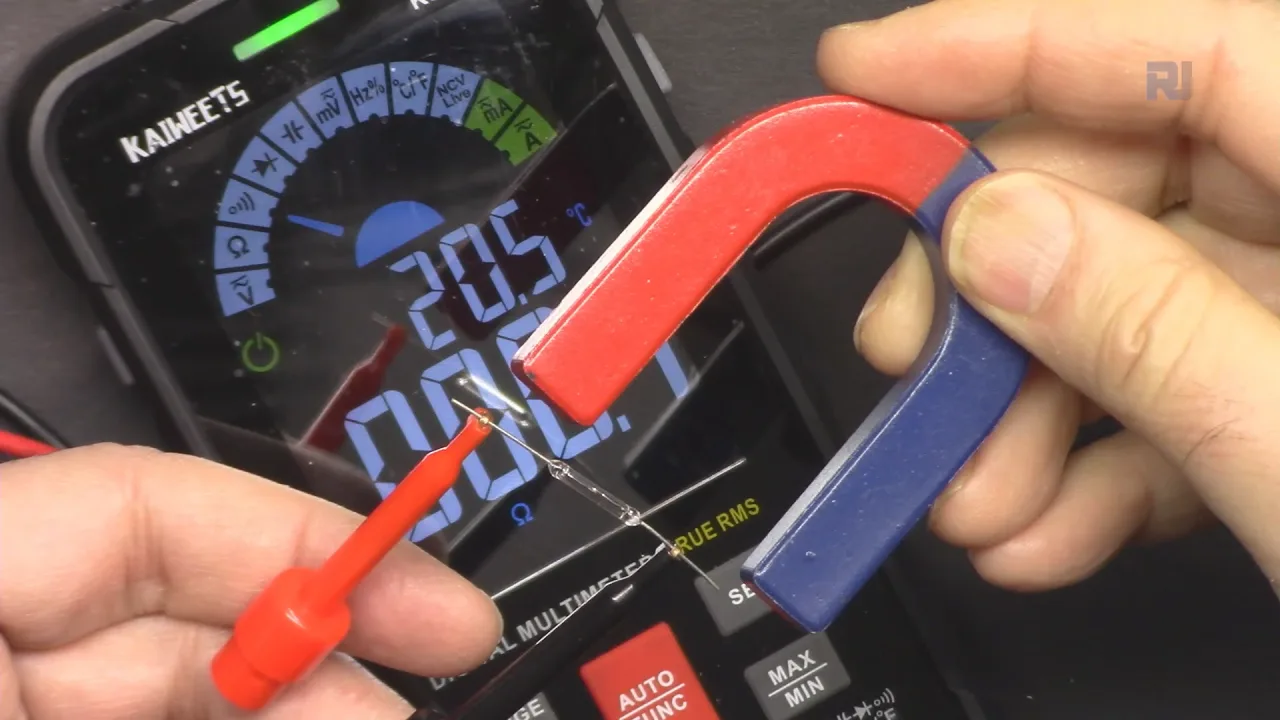
A reed switch is a small glass capsule containing two thin ferromagnetic blades (in video at 12:38). In the presence of a magnetic field the blades are attracted to each other and touch, closing the circuit. Remove the magnet and the blades spring apart, opening the circuit again. That is the entire principle — it is a switch with no moving button, no wear from finger presses, and no need for physical contact with the object you are sensing.
You can verify this behaviour with a multimeter in continuity mode (in video at 13:59): with no magnet nearby the meter shows an open circuit, and as soon as a magnet approaches the buzzer sounds and the meter reads a closed circuit. Because the switch is electrically identical to a push button, the Arduino code and wiring are the same as any other digital input.
Digital Inputs and Pull Resistors Explained
The Arduino reads a digital pin as either HIGH or LOW. On a 5 V board, anything above roughly 2.2 V is treated as HIGH and anything below about 1.5 V as LOW (in video at 01:49). The problem is that a switch connected directly between a pin and 5 V leaves the pin floating when the switch is open — it is connected to nothing, so it picks up noise and reports random values.
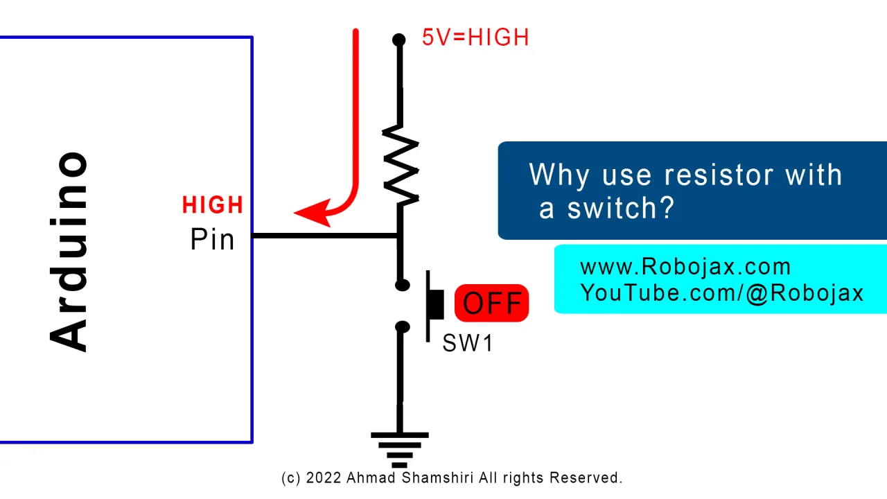
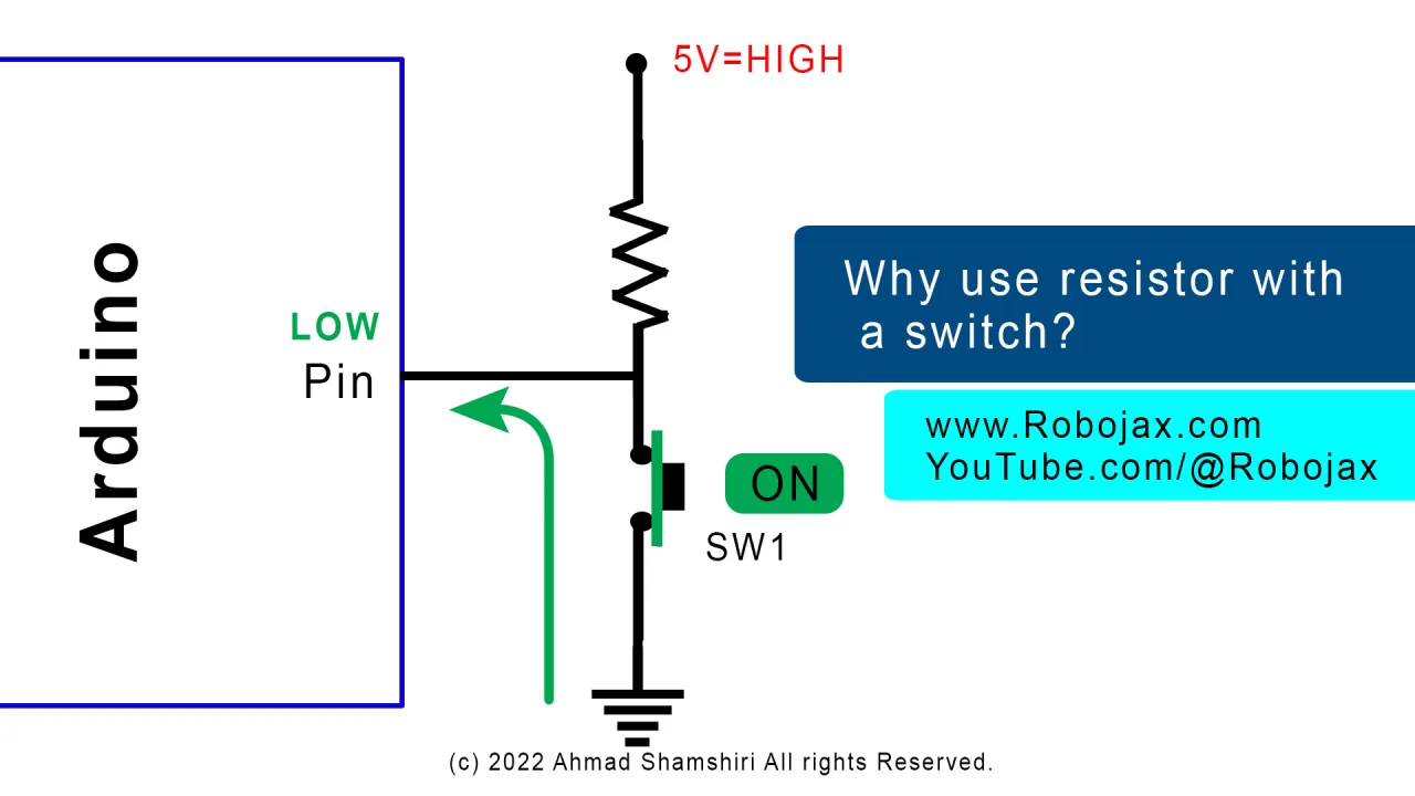
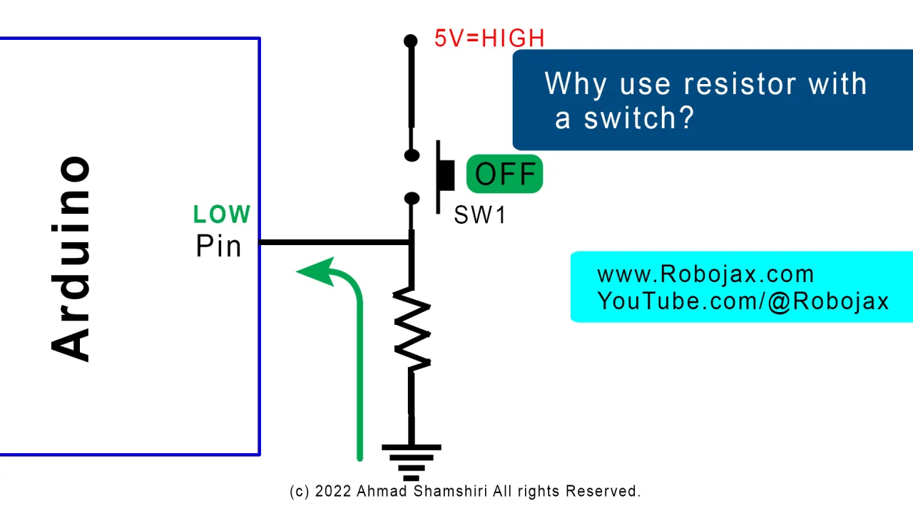
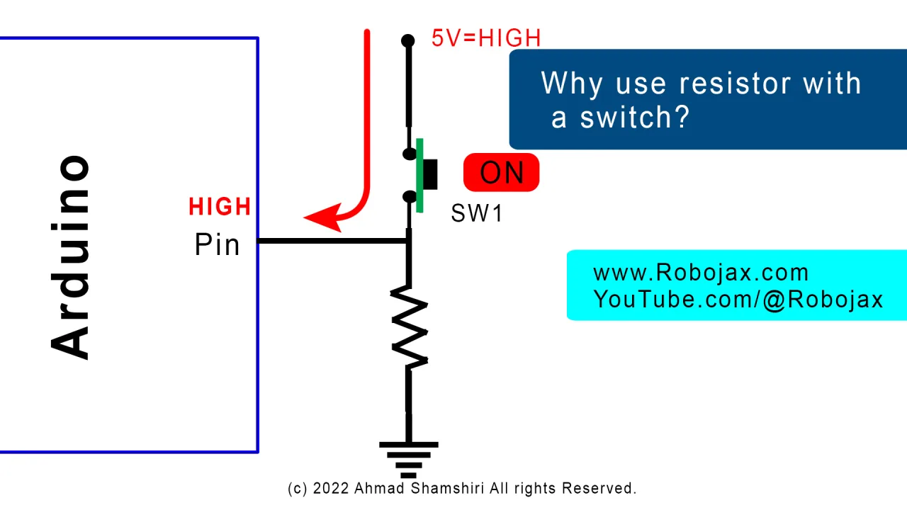
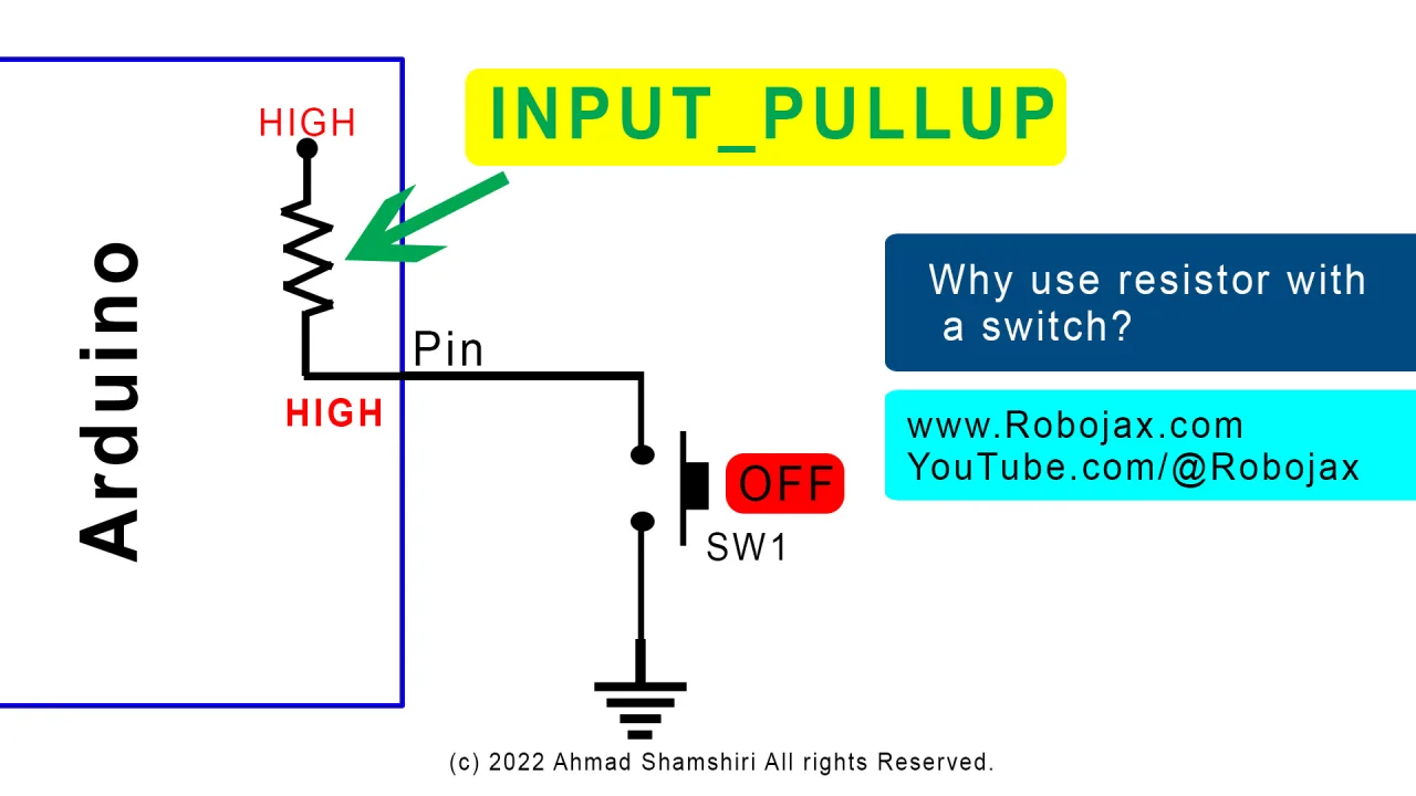
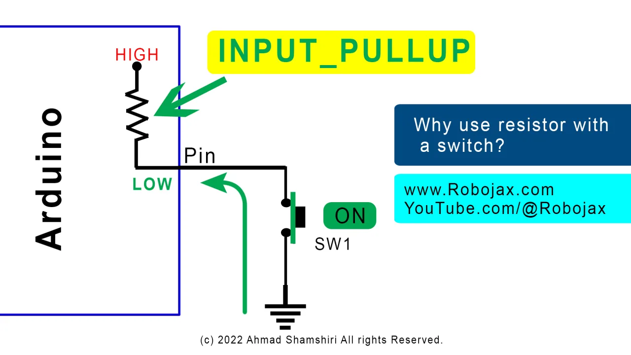


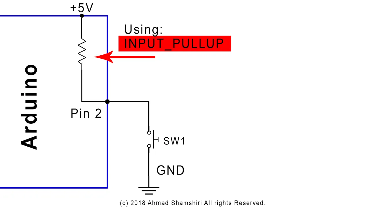
That is why a resistor is used. Two arrangements work equally well:
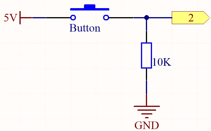
- Pull-down: a 10 kΩ resistor from the pin to ground. The pin reads LOW when the switch is open and HIGH when the switch connects the pin to 5 V.
- Pull-up: a 10 kΩ resistor from the pin to 5 V. The pin reads HIGH when the switch is open and LOW when the switch connects the pin to ground.
The Arduino also has an internal pull-up resistor that can be enabled in software with INPUT_PULLUP (in video at 19:52). This removes the need for the external resistor completely — the pin idles HIGH, and closing the switch to ground pulls it LOW. The trade-off is that the logic is inverted: pressed (or magnet present) now reads 0 instead of 1.
Hardware and Components
- Arduino Uno (or any compatible board)
- Reed switch module or bare reed switch
- 10 kΩ resistor (only needed for the pull-down version)
- Breadboard and jumper wires
- A small magnet for testing
- USB cable for programming and power
Wiring Guide
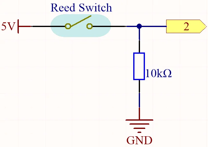
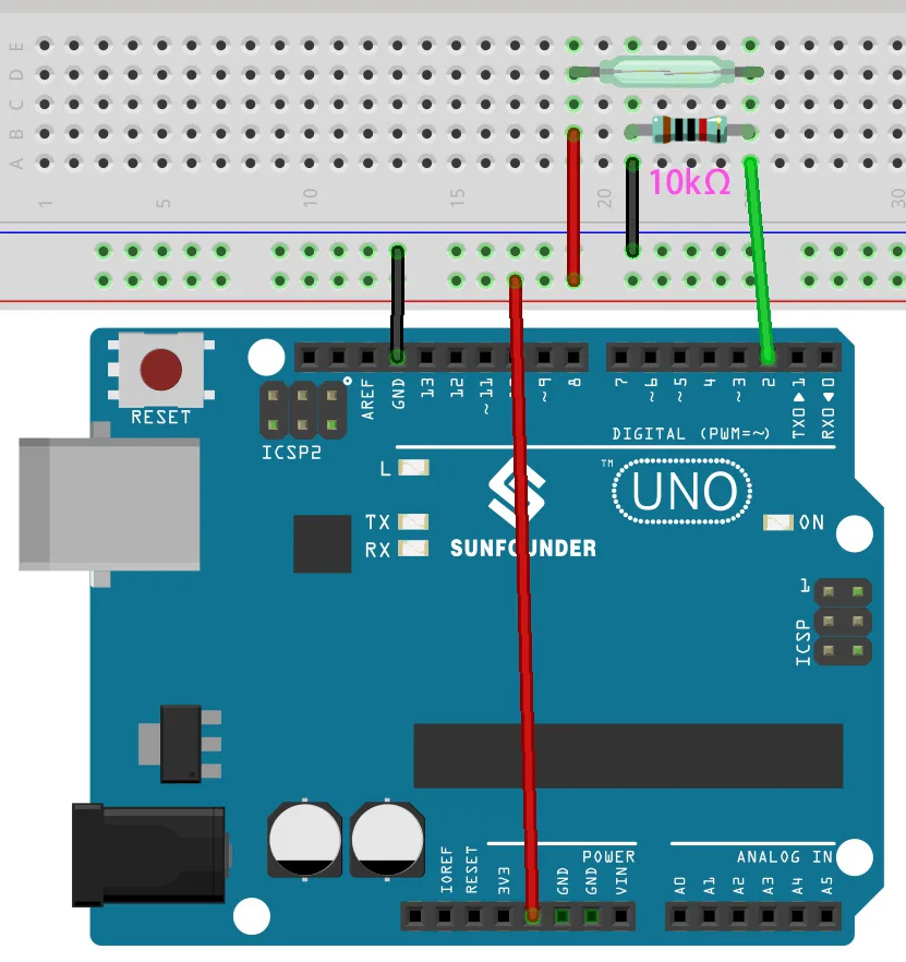
The reed switch is wired exactly like a push button. One leg of the reed switch goes to 5 V, the other leg goes to Arduino pin 2 and to one end of the 10 kΩ resistor. The other end of the resistor goes to ground (in video at 14:40). This is a pull-down configuration, so the pin reads LOW with no magnet present and HIGH when a magnet closes the switch.
On the breadboard, place the reed switch so its two legs sit in different rows, connect the resistor from the same row as one leg down to the ground rail, run a red wire from the other leg to the 5 V rail, and a green wire from the junction of the reed switch and resistor to pin 2 (in video at 15:53). Black goes to ground, red goes to 5 V, green goes to pin 2 — the same colour convention used throughout the SunFounder kit.
If you prefer to skip the resistor, wire one leg of the reed switch to pin 2 and the other leg straight to ground, then enable INPUT_PULLUP in the code as described below.
Code Explanation
The sketch is intentionally tiny. Everything you will want to change lives in two places at the top of the file.
int reedPin = 2;//the pin reed switch is connected to

void setup() {
  Serial.begin(9600);
  pinMode(reedPin, INPUT);
}
reedPin — change this number if you wired the reed switch to a different digital pin. Any digital pin on the Uno works; pin 2 is used here simply because it is convenient on the breadboard.
Serial.begin(9600) — sets the serial monitor speed. If you change this value you must also change the baud rate dropdown in the Serial Monitor window, otherwise you will see garbage characters (in video at 11:25).
pinMode(reedPin, INPUT) — configures the pin as a high-impedance input so it can sense the voltage set by the reed switch and resistor. If you are using the internal pull-up instead, change this line to pinMode(reedPin, INPUT_PULLUP); and remember that the readings will be inverted.
The loop simply reads the pin and prints the result:
void loop() {
  Serial.println(digitalRead(reedPin));
  delay(10);
}
digitalRead(reedPin) returns 1 when the pin is HIGH and 0 when it is LOW. Because the value is passed straight into Serial.println(), there is no need for an intermediate variable — the reading is printed directly. With the pull-down wiring, 0 means "no magnetic field" and 1 means "magnet detected" (in video at 18:31).
delay(10) controls how often a reading is printed. Ten milliseconds is fast enough that you will see the value change the instant a magnet approaches. If you prefer a calmer display you can raise it to 200 ms, but note that this slows detection down as well (in video at 12:01).
Live Project Demonstration
After uploading the sketch, open the Serial Monitor and set the baud rate to 9600. With no magnet nearby the window fills with zeros. Bring a small magnet close to the glass capsule and the output immediately switches to ones; pull the magnet away and it returns to zero (in video at 17:04). The response is instantaneous and works even when the magnet is held a centimetre or two away from the switch.
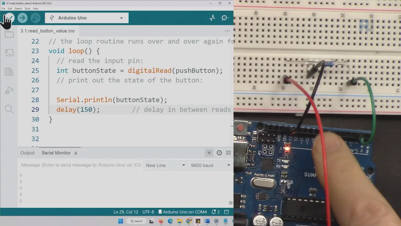
If you built the pull-up version instead, the logic is reversed: the monitor shows 1 at rest and 0 when the magnet is present (in video at 22:13). Either way, you now have a reliable, contactless magnetic field detector that costs almost nothing and can be dropped into any of the project ideas listed at the top of this article.
The push-button version of this same digital-read lesson is covered separately in Lesson 7/31: Digital Read Push button, detecting magnetic field SunFounder Kit | Robojax.
Related projects from this video
Chapters
- [00:00] Introduction: two digital read examples
- [01:33] What digital read and HIGH/LOW mean
- [02:46] How a push button switch works
- [03:25] Pull-up and pull-down resistor theory
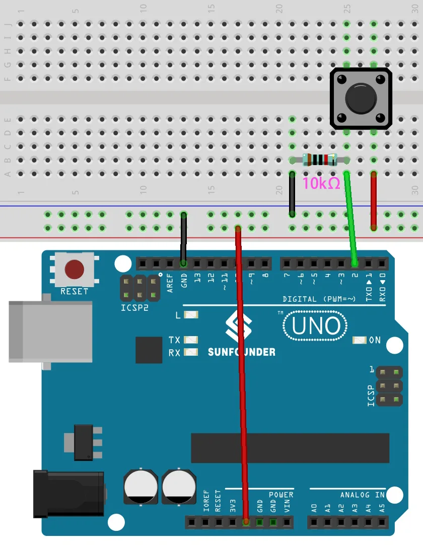
- [05:18] Wiring the push button on the breadboard
- [08:21] Opening and explaining the button sketch
- [10:55] Uploading and testing the button example
- [12:38] Introducing the reed switch and testing it with a multimeter
- [14:40] Wiring the reed switch to pin 2
- [16:46] Testing the reed switch with a magnet
- [17:19] Explaining the reed switch sketch
- [19:45] Using INPUT_PULLUP without an external resistor
圖片
This code has not been parsed yet. Please return to the admin panel to parse it.Common Course Links
Common Course Files
你可能需要嘅嘢
-
亞馬遜Buy reed switch from Amazonamzn.to
-
亞馬遜
-
亞馬遜SunFounder Arduino Learning Kit on AliExpresss.click.aliexpress.com
-
亞馬遜
-
亞馬遜
-
亞馬遜
-
易贝Buy reed switch from eBayebay.us
-
阿里巴巴速卖通Buy reed switch from AliExpresss.click.aliexpress.com
資源與參考資料
-
文件记录Documentation for SunFounder 3 in 1 IoT/Smart Car/Learning Kitdocs.sunfounder.com
-
外部Purchase SunFounder's 3-in-1 Smart car learning kitsunfounder.com
文件📁
Arduino 函式庫 (zip)
-
SunFounder 3合1智能車學習套件原始碼
3in1-kit-main-v2.zip12.80 MB
用户手册
-
SunFounder 3合1 Arduino 智能車組裝手冊呢份文件逐步展示 SunFounder 3合1 Arduino 智能車嘅組裝過程
SunFounder_car_assembly_manual.pdf1.20 MB


![Arduino Starter Kit R4 [K000007_R4] – Learn Electronics and Coding with the UNO R4 WiFi Board, 13 Guided Projects in a Printed Book + Growing Resources Online, Official Certification Voucher](https://m.media-amazon.com/images/I/51mjbAi4hGL._SL75_.jpg)