Lesson 7/31: Digital Read Push button, detecting magnetic field SunFounder Kit | Robojax
Digital inputs are the foundation of almost every interactive electronics project. Whether you want to detect a button press, sense a magnetic field, or trigger an action based on an external event, understanding how to read a digital signal with a microcontroller is an essential skill. In this lesson, we build two practical circuits using the SunFounder 3-in-1 Arduino kit: one that reads a push button and another that detects a magnetic field using a reed switch. Along the way, you will also learn a clever trick that lets you use a push button without any external resistor at all.

These techniques open the door to a wide range of real-world projects, including:
- Building a door or window sensor that triggers an alarm when opened
- Creating a magnetic proximity detector for security or automation
- Adding user input buttons to a menu-driven device
- Detecting the position of a rotating wheel using a magnet and reed switch
- Making a simple counter that increments each time a button is pressed
- Building a bicycle speedometer by counting wheel revolutions with a reed switch
Hardware and Components
To follow along with both examples in this lesson, you will need the following parts, all of which are included in the SunFounder 3-in-1 Arduino kit:
- Arduino board (Uno or compatible)
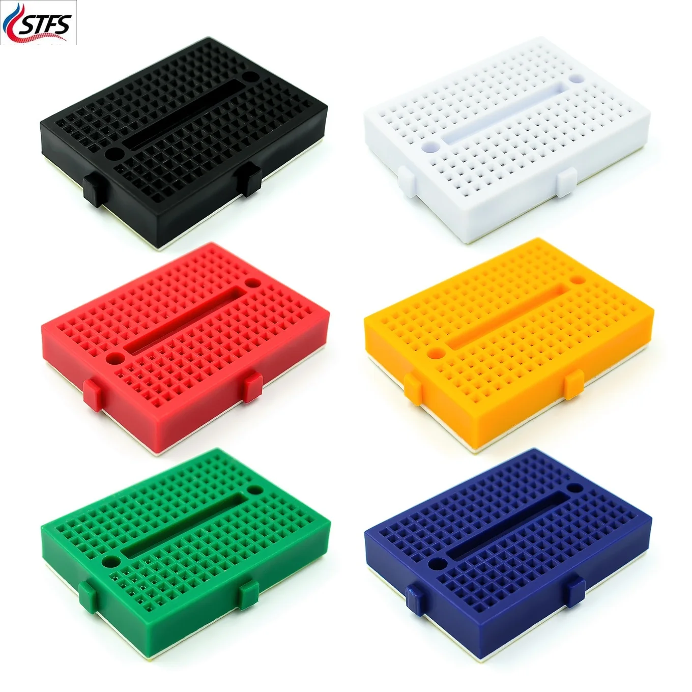
- Breadboard
- Push button switch
- Reed switch (magnetic sensor)
- 10 kΩ resistor
- Small magnet (for testing the reed switch)
- Jumper wires (red, black, green)
- USB cable for programming and power
Optionally, a multimeter such as the KAIWEETS KM601 is helpful for verifying continuity of the reed switch before wiring it up, as demonstrated in the video at 13:00.
Understanding Digital Read
The digitalRead() function in Arduino reads the state of a pin and returns either HIGH or LOW. In a 5 V system, HIGH corresponds to 5 volts and LOW corresponds to 0 volts. As a general rule, voltages above approximately 2.2 V are treated as HIGH, and voltages below about 1.5 V are treated as LOW (in video at 01:49). The function returns these states as 1 and 0 respectively.
A push button is simply a switch that connects two pins when pressed. Without a reference voltage, however, a floating input pin can produce unpredictable readings. That is why a pull-down resistor (connected to ground) or a pull-up resistor (connected to 5 V) is normally required. In this lesson, we use a 10 kΩ resistor connected between the input pin and ground, so the pin reads LOW when the button is not pressed and HIGH when it is pressed.
Wiring Guide
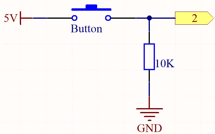
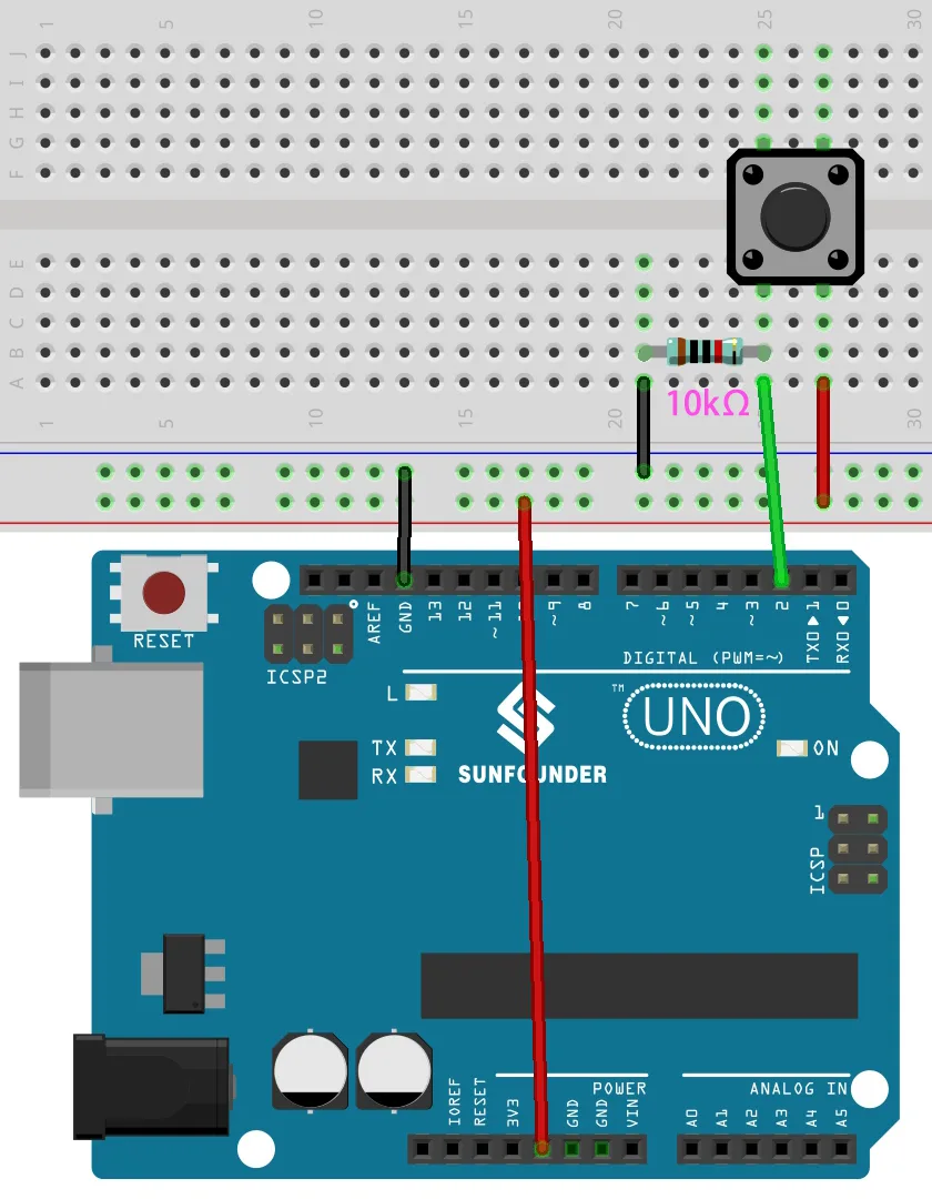
The wiring for the push button example is straightforward. One side of the push button connects to 5 V, and the other side connects to both pin 2 and one leg of the 10 kΩ resistor. The other leg of the resistor connects to ground. This arrangement ensures the pin is pulled low when the button is released and pulled high when pressed.
For the reed switch example, the wiring is nearly identical: the reed switch replaces the push button. One side of the reed switch connects to 5 V, and the other side connects to pin 2 and the 10 kΩ resistor, which then goes to ground. When a magnet is brought near the reed switch, the internal contacts close, connecting the pin to 5 V and producing a HIGH reading.
Code Explanation
The code for both examples is based on the Arduino DigitalReadSerial example. The user-configurable parts are minimal, which makes this a great starting point for beginners.
The first thing to configure is the pin that the button or reed switch is connected to:
// digital pin 2 has a pushbutton attached to it. Give it a name:
int pushButton = 2;
Change the value 2 if you wired your switch to a different digital pin. The variable name can also be changed for clarity — for example, to reedPin when using the reed switch.
In the setup() function, the serial monitor is initialized and the pin is set as an input:
void setup() {
  Serial.begin(9600);
  pinMode(pushButton, INPUT);
}
The baud rate 9600 must match the setting in the Arduino Serial Monitor, or you will see garbled output (in video at 11:25).
Inside loop(), the pin is read and the result is printed:
void loop() {
  int buttonState = digitalRead(pushButton);
  Serial.println(buttonState);
  delay(1);
}
The delay(1) at the end of the loop can be increased if you want slower, more readable output on the serial monitor. In the video, a value of 200 milliseconds is used to make the readings easier to observe (in video at 12:01).
Using INPUT_PULLUP
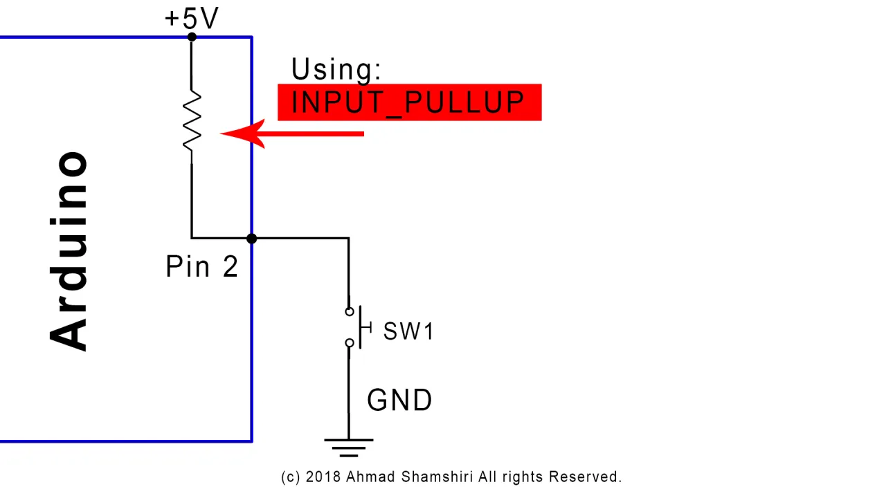
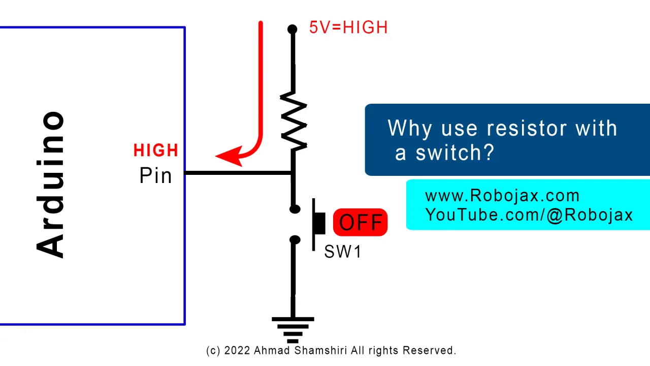
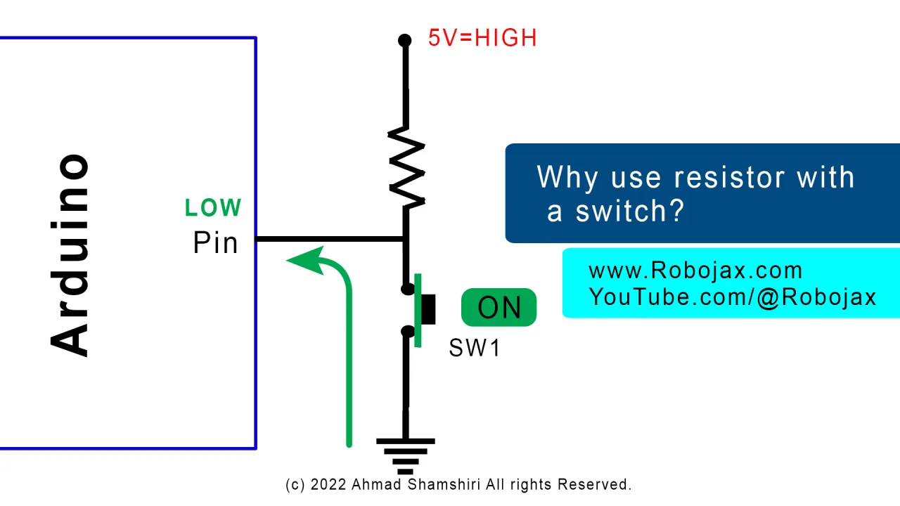
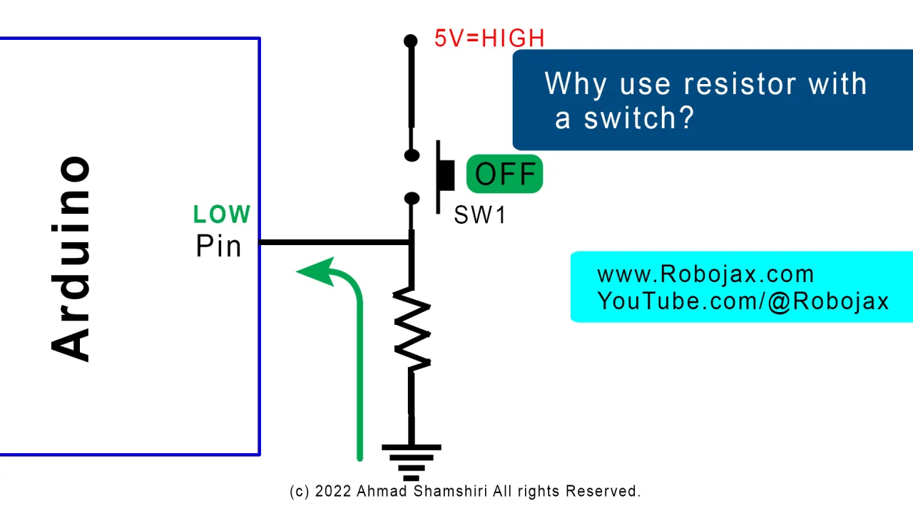
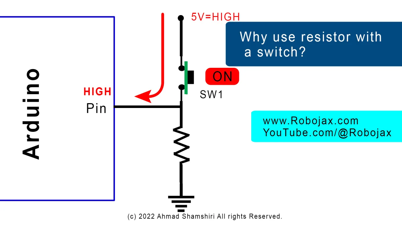
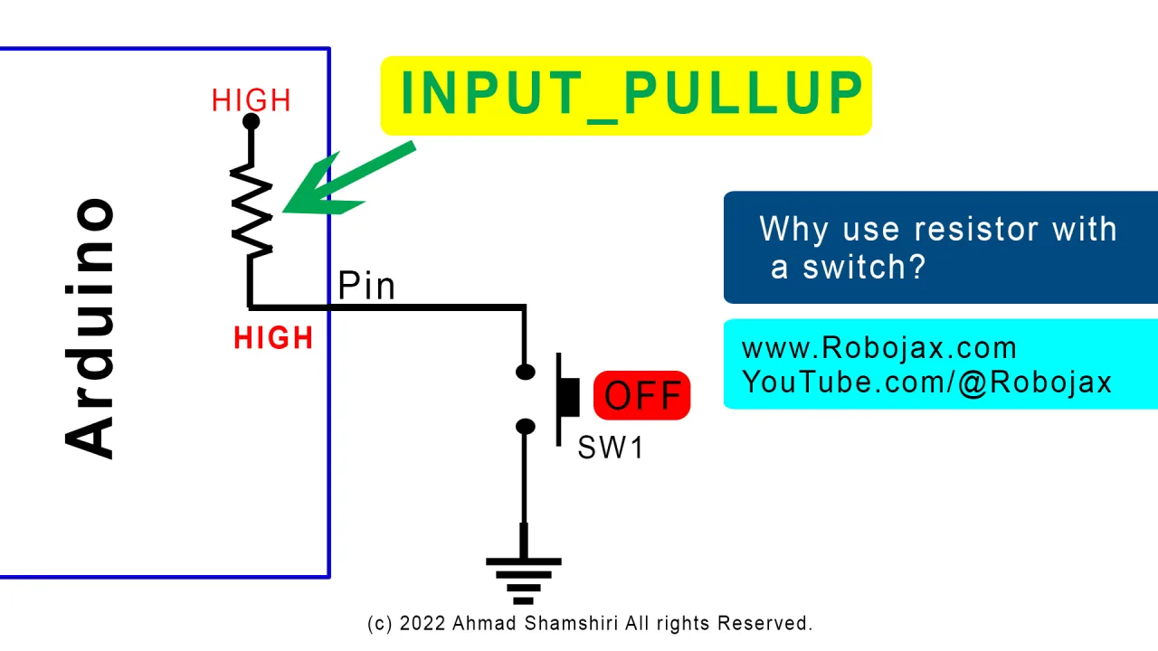
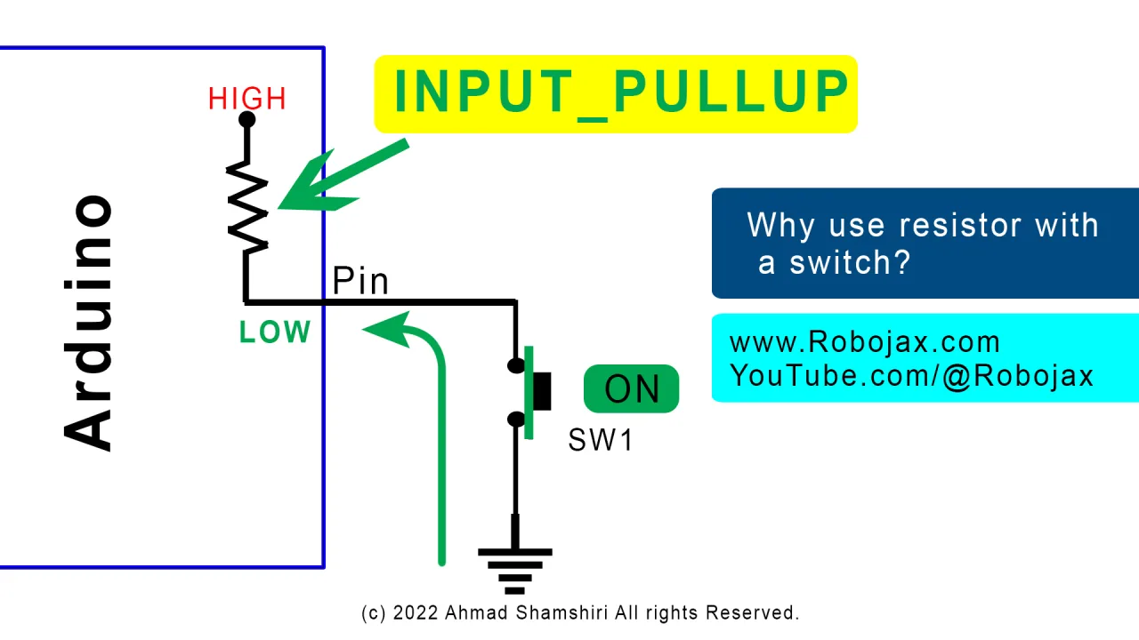


Arduino also supports an internal pull-up resistor, which eliminates the need for an external resistor entirely. To use it, simply change the pin mode:
pinMode(pushButton, INPUT_PULLUP);
With this configuration, wire one side of the push button to pin 2 and the other side directly to ground — no resistor required. The logic is inverted: the pin reads HIGH when the button is not pressed and LOW when it is pressed (in video at 22:13). This is a convenient option when you want to minimize components or save breadboard space.
Live Project Demonstration
After uploading the first sketch, open the Serial Monitor and press the push button. You will see a stream of 0 values that change to 1 while the button is held down (in video at 11:43). Releasing the button returns the reading to 0.
For the reed switch example, the same code is used with the pin renamed. Bring a small magnet close to the reed switch and observe the serial output change from 0 to 1. Remove the magnet and it returns to 0 (in video at 17:12). This demonstrates how a reed switch can reliably detect the presence of a magnetic field from a short distance.
Finally, the INPUT_PULLUP version is demonstrated with a push button wired directly between pin 2 and ground. The serial monitor shows 1 when the button is released and 0 when pressed, confirming that no external resistor is needed (in video at 22:20).
Chapters
- [00:00] Introduction and lesson overview
- [01:33] Understanding digital read: HIGH and LOW states
- [02:46] How a push button switch works
- [03:25] Pull-up and pull-down resistor configurations
- [05:18] Wiring the push button circuit
- [08:21] Opening and explaining the push button code
- [10:55] Uploading and testing the push button example
- [12:38] Introduction to the reed switch and multimeter test
- [14:40] Wiring the reed switch circuit
- [16:46] Testing the reed switch with a magnet
- [19:45] Using INPUT_PULLUP to eliminate the resistor
- [21:49] Uploading and testing the pull-up example
Images
This code has not been parsed yet. Please return to the admin panel to parse it.Common Course Links
Common Course Files
Things you might need
-
AmazonBuy reed switch from Amazonamzn.to
-
Amazon
-
AmazonSunFounder Arduino Learning Kit on AliExpresss.click.aliexpress.com
-
Amazon
-
Amazon
-
Amazon
-
Amazon
-
eBayBuy reed switch from eBayebay.us
-
AliExpressBuy reed switch from AliExpresss.click.aliexpress.com
Resources & references
-
DocumentationDocumentation for SunFounder 3 in 1 IoT/Smart Car/Learning Kitdocs.sunfounder.com
-
ExternalPurchase SunFounder's 3-in-1 Smart car learning kitsunfounder.com
Files📁
Arduino Libraries (zip)
-
SunFounder's 3-in-1 Smart Car learning kit source code
3in1-kit-main-v2.zip12.80 MB
User’s Manual
-
SunFounder 3-in-1 Arduino Smart Car assembly manualThis document shows step by step assembly of SunFounder 3-in-1 Arduino Smart Car
SunFounder_car_assembly_manual.pdf1.20 MB


![Arduino Starter Kit R4 [K000007_R4] – Learn Electronics and Coding with the UNO R4 WiFi Board, 13 Guided Projects in a Printed Book + Growing Resources Online, Official Certification Voucher](https://m.media-amazon.com/images/I/51mjbAi4hGL._SL75_.jpg)