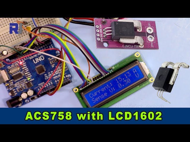
Measuring Current Using an Allegro ACS758 Current Sensor with an LCD1602 for Arduino
This project demonstrates how to measure current using an Allegro ACS758 current sensor and display the readings on an LCD1602 screen connected to an Arduino. The ACS758 is a versatile sensor capable of measuring currents up to 200 Amps, making it suitable for various applications.

This project provides a practical way to monitor current flow in a circuit, which is crucial for various applications, including:
- Monitoring power consumption in appliances
- Building a battery management system
- Designing an electric motor controller
- Creating a current-based security system
This guide will walk you through the necessary hardware, wiring, code, and a live demonstration.
Hardware pins

Hardware/Components
To build this project, you will need the following components:
- Arduino Uno (or compatible)
- Allegro ACS758 Current Sensor (the specific model number will determine the maximum current measurement; ensure to adjust the code accordingly. (in video at 00:14 and 03:18))
- LCD1602 Display without I2C module, the LCD has 12 wries
- Connecting wires
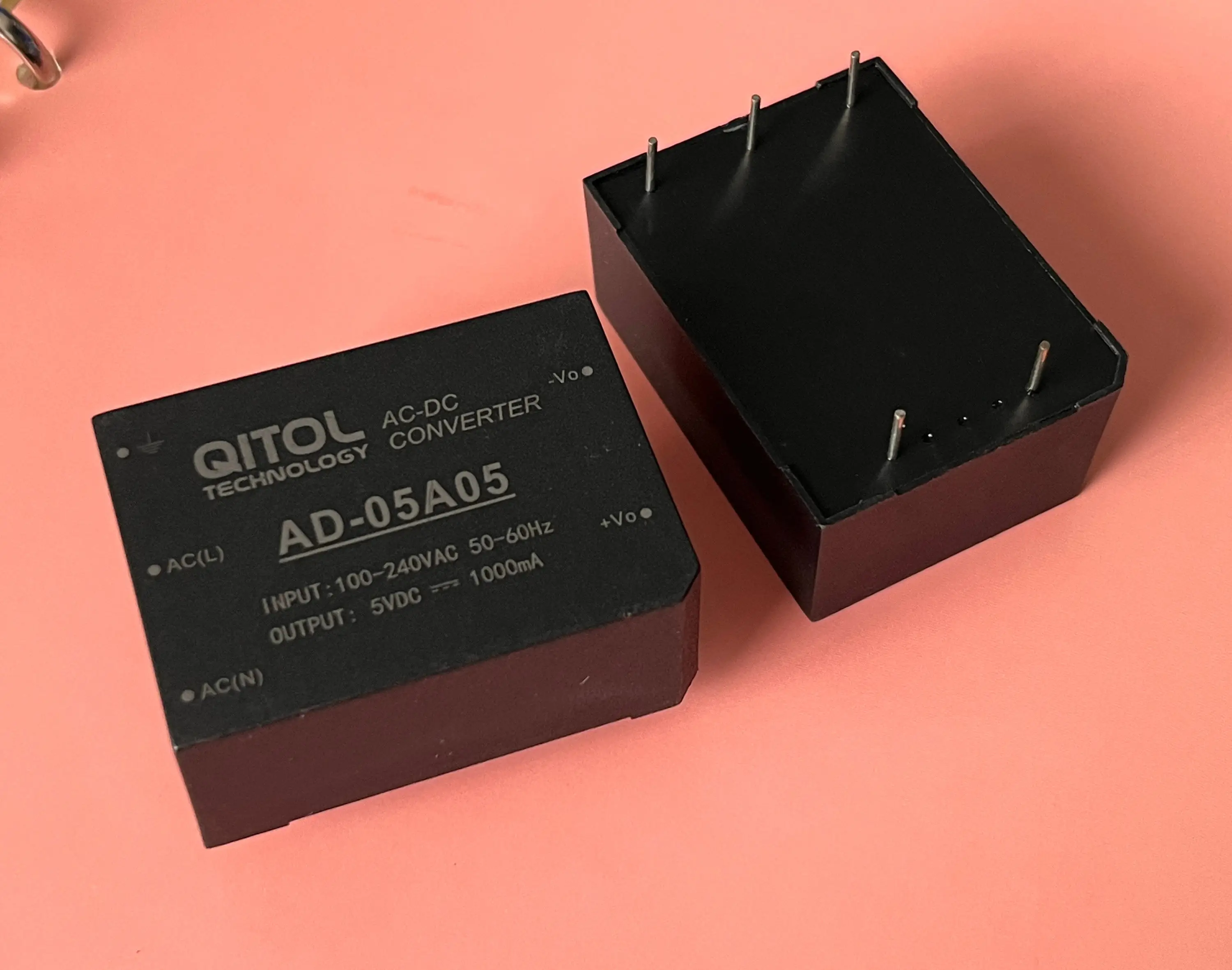
- Power supply (5V)
- Load (for testing the current measurement)

Wiring Guide
")
The wiring for the LCD1602 is explained in a separate video (in video at 01:24). The key connections for this project are as follows (in video at 01:24):
- ACS758: VCC to 5V, GND to GND, Signal Out (yellow wire) to A0 on the Arduino.
- The ACS758 sensor's two main wires are connected in series with the load (in video at 02:09).
Code Explanation
The Arduino code consists of two main parts: one for handling the ACS758 sensor and another for interacting with the LCD1602. The user-configurable parts of the code are:
#define VIN A0 // define the Arduino pin A0 as voltage input (V in)
const float VCC   = 5.0;// supply voltage 5V or 3.3V. If using PCB, set to 5V only.
const int model = 2;   // enter the model (see below)
float cutOffLimit = 1.00;// reading cutoff current. 1.00 is 1 Amper
The model variable needs to be set according to the specific ACS758 model used (in video at 03:18). Refer to the code comments for the model number mapping. The cutOffLimit variable determines the minimum current to be displayed (in video at 03:48). Adjust this value to filter out insignificant readings.
Live Project/Demonstration
The video demonstrates how to connect the ammeter to measure the current flowing through the load (in video at 02:18). The code displays the current and voltage readings on both the LCD1602 and the serial monitor (in video at 07:02). The demonstration shows how the readings update dynamically as the load current changes (in video at 07:14). It also highlights that when the current falls below the specified limit, "No Current" is displayed (in video at 07:59).
Chapters
- [00:06] Introduction
- [00:34] Prerequisites
- [01:24] Wiring Explanation
- [02:18] Current Measurement Demonstration
- [02:57] Code Explanation
- [07:02] Live Demonstration
- [08:18] Conclusion
图像
This code has not been parsed yet. Please return to the admin panel to parse it.|||您可能需要的东西
-
亚马逊从亚马逊购买Allegro ACS758电流传感器amzn.to
-
易趣从eBay购买Allegro ACS758电流传感器ebay.us
-
全球速卖通从AliExpress购买Allegro ACS758电流传感器s.click.aliexpress.com
资源与参考
文件📁
没有可用的文件。