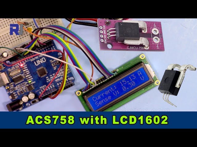
Allegro ACS758電流センサとLCD1602を用いたArduinoでの電流測定
このプロジェクトでは、AllegroのACS758電流センサを使用して電流を測定し、Arduinoに接続したLCD1602画面に測定値を表示する方法を示します。ACS758は最大200アンペアまでの電流を測定できる汎用性の高いセンサで、さまざまな用途に適しています。

このプロジェクトは、回路内の電流の流れを監視する実用的な方法を提供します。これは、以下を含むさまざまな用途にとって重要です:
- 家電製品の消費電力の監視
- バッテリーマネジメントシステムの構築
- 電動モーターコントローラの設計
- 電流に基づくセキュリティシステムの構築
このガイドでは、必要なハードウェア、配線、コード、および実演を順を追って説明します。
ハードウェアピン

ハードウェア/コンポーネント
このプロジェクトをビルドするには、次のコンポーネントが必要です:
- Arduino Uno(または互換機)
- Allegro ACS758 電流センサー(特定の型番により最大測定電流が決まるため、コードをそれに合わせて調整してください。(動画の00:14と03:18で))
- I2CモジュールなしのLCD1602ディスプレイ,そのLCDには12本の配線があります
- 接続用配線
- 電源(5V)
- 負荷(電流測定用)

配線ガイド
")
LCD1602の配線は別のビデオで説明されています(ビデオの01:24参照)。このプロジェクトの主要な接続は次のとおりです(ビデオの01:24参照):
- ACS758:VCCを5Vに、GNDをGNDに、Signal Out(黄色い線)をArduinoのA0に接続。
- ACS758センサーの2本の主配線は負荷と直列に接続されています(動画の02:09で)。
コードの説明
Arduinoのコードは2つの主要な部分で構成されています。1つはACS758センサーの処理用、もう1つはLCD1602とのやり取り用です。ユーザーが設定可能なコードの部分は次のとおりです:
#define VIN A0 // define the Arduino pin A0 as voltage input (V in)
const float VCC   = 5.0;// supply voltage 5V or 3.3V. If using PCB, set to 5V only.
const int model = 2;   // enter the model (see below)
float cutOffLimit = 1.00;// reading cutoff current. 1.00 is 1 Amper
Themodel変数は使用している特定のACS758モデルに合わせて設定する必要があります(動画の03:18で確認できます)。モデル番号の対応はコードのコメントを参照してください。そのcutOffLimit変数は表示される最小電流を決定します(動画の03:48で)。この値を調整して重要でない読み取り値を除外してください。
ライブプロジェクト/デモンストレーション
この動画では、電流計を負荷に接続して負荷を流れる電流を測定する方法を示しています(動画の02:18で)。コードはLCD1602とシリアルモニターの両方に電流と電圧の読み値を表示します(動画の07:02で)。デモは、負荷電流が変化するにつれて読み値が動的に更新される様子を示しています(動画の07:14で)。また、電流が設定した制限値を下回ったときに「No Current」と表示されることも強調しています(動画の07:59で)。
章
- [00:06] イントロダクション
- [00:34] 前提条件
- [01:24] 配線の説明
- [02:18] 電流測定の実演
- [02:57] コードの説明
- [07:02] ライブデモンストレーション
- [08:18] 結論
画像
/*
 *
 * Arduino Sketch for Allegro ACS758 Current Sensor with LCD1602
 * This sensor can measure current at a range of up to 200A.
 * It operates with 3.3V or 5V.
 * This sketch requires you to watch the following two videos before using this code:
 * 1- ACS758 Sensor https://www.youtube.com/watch?v=SiHfjzcqnU4
 * 2- LCD1602 Display https://www.youtube.com/watch?v=S4ya3Q7uhJs
 *
 *
 * Written by Ahmad Shamshiri on Tuesday, June 22, 2018 at 17:57 in Ajax, Ontario, Canada
 * for Robojax.com
 * View the video instruction for this code at https://youtu.be/Co-DrCa2slk
 * This code has been downloaded from Robojax.com
 */
#define VIN A0 // define the Arduino pin A0 as voltage input (V in)
const float VCC   = 5.0;// supply voltage 5V or 3.3V. If using PCB, set to 5V only.
const int model = 2;   // enter the model (see below)

float cutOffLimit = 1.00;// reading cutoff current. 1.00 is 1 Amper

/*
          "ACS758LCB-050B",// for model use 0
          "ACS758LCB-050U",// for model use 1
          "ACS758LCB-100B",// for model use 2
          "ACS758LCB-100U",// for model use 3
          "ACS758KCB-150B",// for model use 4
          "ACS758KCB-150U",// for model use 5
          "ACS758ECB-200B",// for model use 6
          "ACS758ECB-200U"// for model use 7
Sensitivity array is holding the sensitivity of the ACS758
current sensors. Do not change.
*/
float sensitivity[] ={
          40.0,// for ACS758LCB-050B
          60.0,// for ACS758LCB-050U
          20.0,// for ACS758LCB-100B
          40.0,// for ACS758LCB-100U
          13.3,// for ACS758KCB-150B
          16.7,// for ACS758KCB-150U
          10.0,// for ACS758ECB-200B
          20.0,// for ACS758ECB-200U
         };

/*
 *   Quiescent output voltage is a factor of VCC that appears at the output
 *   when the current is zero.
 *   For bidirectional sensors it is 0.5 x VCC.
 *   For unidirectional sensors it is 0.12 x VCC.
 *   For model ACS758LCB-050B, the B at the end represents Bidirectional (polarity doesn't matter).
 *   For model ACS758LCB-100U, the U at the end represents Unidirectional (polarity must match).
 *   Do not change.
 */
float quiescent_Output_voltage [] ={
          0.5,// for ACS758LCB-050B
          0.12,// for ACS758LCB-050U
          0.5,// for ACS758LCB-100B
          0.12,// for ACS758LCB-100U
          0.5,// for ACS758KCB-150B
          0.12,// for ACS758KCB-150U
          0.5,// for ACS758ECB-200B
          0.12,// for ACS758ECB-200U
          };
const float FACTOR = sensitivity[model]/1000;// set sensitivity for selected model
const float QOV =   quiescent_Output_voltage [model] * VCC;// set quiescent Output voltage for selected model
float voltage;// internal variable for voltage
float cutOff = FACTOR/cutOffLimit;// convert current cut off to mV
 //************ END of ACS785 Settings

//******************** Start of LCD1602
// January 21, 2018 14:25
// original source https://www.arduino.cc/en/Tutorial/HelloWorld
// include the library code:
#include <LiquidCrystal.h>

// initialize the library by associating any needed LCD interface pin
// with the arduino pin number it is connected to
const int rs = 12, en = 11, d4 = 5, d5 = 4, d6 = 3, d7 = 2;
LiquidCrystal lcd(rs, en, d4, d5, d6, d7);

void setup() {
  // Robojax.com ACS758 Current Sensor with LCD1602
    Serial.begin(9600);// initialize serial monitor
    Serial.println("Robojax Tutorial");
    Serial.println("ACS758 Current Sensor");
    Serial.println("with LCD1602 display");
  // set up the LCD's number of columns and rows:
  lcd.begin(16, 2);
  // Print a message to the LCD.
    lcd.clear();
  lcd.print("Robojax");
  lcd.setCursor (0,1); // go to start of 2nd line
  lcd.print("ACS758 Current Sensor");
  delay(2000);
  lcd.clear();
}

void loop() {
  // Robojax.com ACS758 Current Sensor with LCD1602

  float voltage_raw =   (5.0 / 1023.0)* analogRead(VIN);// Read the voltage from sensor
  voltage =  voltage_raw - QOV + 0.007 ;// 0.007 is a value to make voltage zero when there is no current
  float current = voltage / FACTOR;
  if(abs(voltage) > cutOff ){
    Serial.print("V: ");
    Serial.print(voltage,3);// print voltage with 3 decimal places
    Serial.print("V, I: ");
    Serial.print(current,2); // print the current with 2 decimal places
    Serial.println("A");
  //start of loop Robojax code ACS758 with LCD1602 and I2C
  lcd.clear();
  lcd.setCursor (0,0); // set to line 1, char 0
  lcd.print("Current: ");
  lcd.setCursor (9,0); // go to start of 2nd line
  lcd.print(current);
  lcd.setCursor (15,0); // go to start of 2nd line
  lcd.print("A");

  lcd.setCursor (0,1);
  lcd.print("Sense V: ");
  lcd.setCursor (9,1); // go to start of 2nd line
  lcd.print(voltage);
  lcd.setCursor (15,1); // go to start of 2nd line
  lcd.print("V");

 //end of loopcode Robojax code ACS758 with LCD1602 and I2C


  }else{
    Serial.println("No Current");
  lcd.clear();
  lcd.setCursor (0,0);
  lcd.print("No Current");
  }


  delay(500);
  // Robojax.com ACS758 Current Sensor with LCD1602
}
必要かもしれないもの
-
アマゾンAmazonでAllegro ACS758電流センサーを購入するamzn.to
-
イーベイeBayからAllegro ACS758電流センサーを購入ebay.us
-
アリエクスプレスAliExpressでAllegro ACS758電流センサーを購入するs.click.aliexpress.com
リソースと参考文献
ファイル📁
ファイルは利用できません。