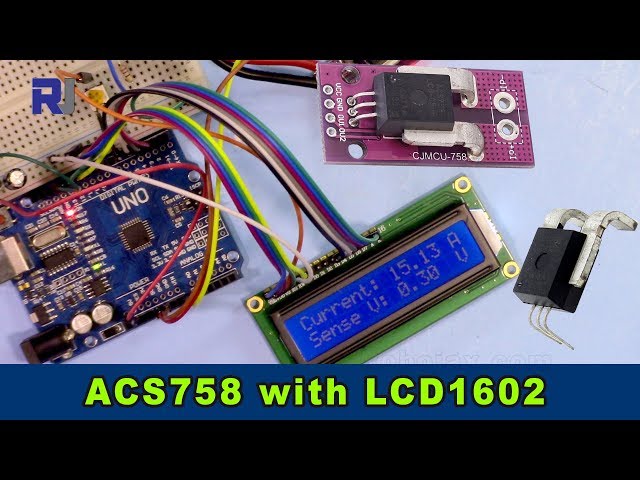
Misurazione della corrente usando il sensore di corrente Allegro ACS758 con un LCD1602 per Arduino
Questo progetto dimostra come misurare la corrente utilizzando un sensore di corrente Allegro ACS758 e visualizzare le letture su uno schermo LCD1602 collegato a un Arduino. L'ACS758 è un sensore versatile in grado di misurare correnti fino a 200 A, rendendolo adatto a varie applicazioni.

Questo progetto offre un modo pratico per monitorare il flusso di corrente in un circuito, che è fondamentale per varie applicazioni, tra cui:
- Monitoraggio del consumo energetico negli elettrodomestici
- Costruire un sistema di gestione della batteria
- Progettazione di un controller per motore elettrico
- Creazione di un sistema di sicurezza basato sulla corrente
Questa guida ti guiderà attraverso l'hardware necessario, il cablaggio, il codice e una dimostrazione dal vivo.
Pin hardware

Hardware/Componenti
Per costruire questo progetto, avrai bisogno dei seguenti componenti:
- Arduino Uno (o compatibile)
- Sensore di corrente Allegro ACS758 (il numero di modello specifico determinerà la corrente massima misurabile; assicurati di adattare il codice di conseguenza. (nel video a 00:14 e 03:18))
- Display LCD1602 senza modulo I2C,Il display LCD ha 12 fili.
- Fili di collegamento
- Alimentatore (5V)
- Carico (per testare la misurazione della corrente)

Guida al cablaggio
")
Il cablaggio per l'LCD1602 è spiegato in un video separato (nel video al 01:24). Le connessioni principali per questo progetto sono le seguenti (nel video al 01:24):
- ACS758: VCC a 5V, GND a GND, uscita segnale (filo giallo) al pin A0 dell'Arduino.
- I due fili principali del sensore ACS758 sono collegati in serie con il carico (nel video a 02:09).
Spiegazione del codice
Il codice Arduino è composto da due parti principali: una per gestire il sensore ACS758 e un'altra per interagire con l'LCD1602. Le parti del codice configurabili dall'utente sono:
#define VIN A0 // define the Arduino pin A0 as voltage input (V in)
const float VCC   = 5.0;// supply voltage 5V or 3.3V. If using PCB, set to 5V only.
const int model = 2;   // enter the model (see below)
float cutOffLimit = 1.00;// reading cutoff current. 1.00 is 1 Amper
IlmodelLa variabile deve essere impostata in base al modello specifico di ACS758 utilizzato (nel video a 03:18). Fare riferimento ai commenti nel codice per la mappatura dei numeri di modello. IlcutOffLimitLa variabile determina la corrente minima da visualizzare (nel video a 03:48). Regola questo valore per filtrare letture insignificanti.
Progetto/Dimostrazione dal vivo
Il video mostra come collegare l'amperometro per misurare la corrente che scorre attraverso il carico (nel video a 02:18). Il codice visualizza le letture di corrente e tensione sia sull'LCD1602 sia sul monitor seriale (nel video a 07:02). La dimostrazione mostra come le letture si aggiornano dinamicamente al variare della corrente del carico (nel video a 07:14). Viene inoltre evidenziato che quando la corrente scende al di sotto del limite specificato, viene visualizzato "No Current" (nel video a 07:59).
Capitoli
- [00:06] Introduzione
- [00:34] Prerequisiti
- [01:24] Spiegazione del cablaggio
- [02:18] Dimostrazione della misurazione della corrente
- [02:57] Spiegazione del codice
- [07:02] Dimostrazione dal vivo
- [08:18] Conclusione
Immagini
/*
 *
 * Arduino Sketch for Allegro ACS758 Current Sensor with LCD1602
 * This sensor can measure current at a range of up to 200A.
 * It operates with 3.3V or 5V.
 * This sketch requires you to watch the following two videos before using this code:
 * 1- ACS758 Sensor https://www.youtube.com/watch?v=SiHfjzcqnU4
 * 2- LCD1602 Display https://www.youtube.com/watch?v=S4ya3Q7uhJs
 *
 *
 * Written by Ahmad Shamshiri on Tuesday, June 22, 2018 at 17:57 in Ajax, Ontario, Canada
 * for Robojax.com
 * View the video instruction for this code at https://youtu.be/Co-DrCa2slk
 * This code has been downloaded from Robojax.com
 */
#define VIN A0 // define the Arduino pin A0 as voltage input (V in)
const float VCC   = 5.0;// supply voltage 5V or 3.3V. If using PCB, set to 5V only.
const int model = 2;   // enter the model (see below)

float cutOffLimit = 1.00;// reading cutoff current. 1.00 is 1 Amper

/*
          "ACS758LCB-050B",// for model use 0
          "ACS758LCB-050U",// for model use 1
          "ACS758LCB-100B",// for model use 2
          "ACS758LCB-100U",// for model use 3
          "ACS758KCB-150B",// for model use 4
          "ACS758KCB-150U",// for model use 5
          "ACS758ECB-200B",// for model use 6
          "ACS758ECB-200U"// for model use 7
Sensitivity array is holding the sensitivity of the ACS758
current sensors. Do not change.
*/
float sensitivity[] ={
          40.0,// for ACS758LCB-050B
          60.0,// for ACS758LCB-050U
          20.0,// for ACS758LCB-100B
          40.0,// for ACS758LCB-100U
          13.3,// for ACS758KCB-150B
          16.7,// for ACS758KCB-150U
          10.0,// for ACS758ECB-200B
          20.0,// for ACS758ECB-200U
         };

/*
 *   Quiescent output voltage is a factor of VCC that appears at the output
 *   when the current is zero.
 *   For bidirectional sensors it is 0.5 x VCC.
 *   For unidirectional sensors it is 0.12 x VCC.
 *   For model ACS758LCB-050B, the B at the end represents Bidirectional (polarity doesn't matter).
 *   For model ACS758LCB-100U, the U at the end represents Unidirectional (polarity must match).
 *   Do not change.
 */
float quiescent_Output_voltage [] ={
          0.5,// for ACS758LCB-050B
          0.12,// for ACS758LCB-050U
          0.5,// for ACS758LCB-100B
          0.12,// for ACS758LCB-100U
          0.5,// for ACS758KCB-150B
          0.12,// for ACS758KCB-150U
          0.5,// for ACS758ECB-200B
          0.12,// for ACS758ECB-200U
          };
const float FACTOR = sensitivity[model]/1000;// set sensitivity for selected model
const float QOV =   quiescent_Output_voltage [model] * VCC;// set quiescent Output voltage for selected model
float voltage;// internal variable for voltage
float cutOff = FACTOR/cutOffLimit;// convert current cut off to mV
 //************ END of ACS785 Settings

//******************** Start of LCD1602
// January 21, 2018 14:25
// original source https://www.arduino.cc/en/Tutorial/HelloWorld
// include the library code:
#include <LiquidCrystal.h>

// initialize the library by associating any needed LCD interface pin
// with the arduino pin number it is connected to
const int rs = 12, en = 11, d4 = 5, d5 = 4, d6 = 3, d7 = 2;
LiquidCrystal lcd(rs, en, d4, d5, d6, d7);

void setup() {
  // Robojax.com ACS758 Current Sensor with LCD1602
    Serial.begin(9600);// initialize serial monitor
    Serial.println("Robojax Tutorial");
    Serial.println("ACS758 Current Sensor");
    Serial.println("with LCD1602 display");
  // set up the LCD's number of columns and rows:
  lcd.begin(16, 2);
  // Print a message to the LCD.
    lcd.clear();
  lcd.print("Robojax");
  lcd.setCursor (0,1); // go to start of 2nd line
  lcd.print("ACS758 Current Sensor");
  delay(2000);
  lcd.clear();
}

void loop() {
  // Robojax.com ACS758 Current Sensor with LCD1602

  float voltage_raw =   (5.0 / 1023.0)* analogRead(VIN);// Read the voltage from sensor
  voltage =  voltage_raw - QOV + 0.007 ;// 0.007 is a value to make voltage zero when there is no current
  float current = voltage / FACTOR;
  if(abs(voltage) > cutOff ){
    Serial.print("V: ");
    Serial.print(voltage,3);// print voltage with 3 decimal places
    Serial.print("V, I: ");
    Serial.print(current,2); // print the current with 2 decimal places
    Serial.println("A");
  //start of loop Robojax code ACS758 with LCD1602 and I2C
  lcd.clear();
  lcd.setCursor (0,0); // set to line 1, char 0
  lcd.print("Current: ");
  lcd.setCursor (9,0); // go to start of 2nd line
  lcd.print(current);
  lcd.setCursor (15,0); // go to start of 2nd line
  lcd.print("A");

  lcd.setCursor (0,1);
  lcd.print("Sense V: ");
  lcd.setCursor (9,1); // go to start of 2nd line
  lcd.print(voltage);
  lcd.setCursor (15,1); // go to start of 2nd line
  lcd.print("V");

 //end of loopcode Robojax code ACS758 with LCD1602 and I2C


  }else{
    Serial.println("No Current");
  lcd.clear();
  lcd.setCursor (0,0);
  lcd.print("No Current");
  }


  delay(500);
  // Robojax.com ACS758 Current Sensor with LCD1602
}
Cose di cui potresti avere bisogno
-
Amazon
-
AliExpressAcquista il sensore di corrente Allegro ACS758 da AliExpresss.click.aliexpress.com
Risorse e riferimenti
File📁
Nessun file disponibile.