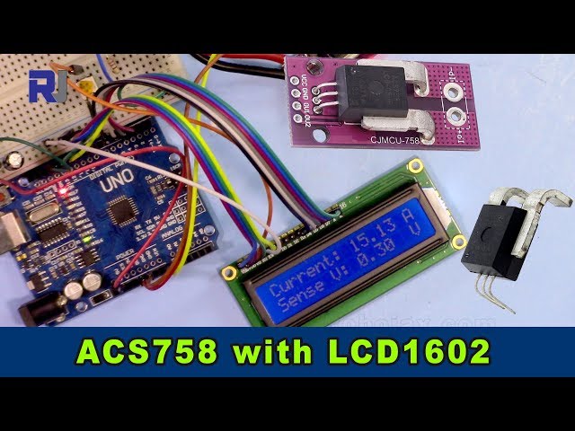
Strommessung mit einem Allegro ACS758-Stromsensor und einem LCD1602 für Arduino
Dieses Projekt zeigt, wie man mit einem Allegro ACS758-Stromsensor Strom misst und die Messwerte auf einem an einen Arduino angeschlossenen LCD1602-Display anzeigt. Der ACS758 ist ein vielseitiger Sensor, der Ströme bis zu 200 Ampere messen kann und sich daher für verschiedene Anwendungen eignet.

Dieses Projekt bietet eine praktische Möglichkeit, den Stromfluss in einem Stromkreis zu überwachen, was für verschiedene Anwendungen wichtig ist, einschließlich:
- Überwachung des Stromverbrauchs in Geräten
- Ein Batteriemanagementsystem bauen
- Entwicklung eines Reglers für Elektromotoren
- Entwicklung eines strombasierten Sicherheitssystems
Dieser Leitfaden führt Sie durch die erforderliche Hardware, die Verkabelung, den Code und eine Live-Demonstration.
Hardware-Pins

Hardware/Komponenten
Um dieses Projekt zu bauen, benötigen Sie die folgenden Komponenten:
- Arduino Uno (oder kompatibel)
- Allegro ACS758 Stromsensor (die genaue Modellnummer bestimmt die maximal messbare Stromstärke; stellen Sie sicher, dass Sie den Code entsprechend anpassen. (im Video bei 00:14 und 03:18))
- LCD1602-Display ohne I2C-Modul,Das LCD hat 12 Drähte.
- Anschlusskabel
- Stromversorgung (5 V)
- Last (zum Testen der Strommessung)

Verdrahtungsanleitung
")
Die Verkabelung für das LCD1602 wird in einem separaten Video erklärt (im Video bei 01:24). Die wichtigsten Verbindungen für dieses Projekt sind wie folgt (im Video bei 01:24):
- ACS758: VCC an 5V, GND an GND, Signal Out (gelbes Kabel) an A0 am Arduino.
- Die beiden Hauptleitungen des ACS758-Sensors sind in Reihe mit der Last geschaltet (im Video bei 02:09).
Erklärung des Codes
Der Arduino-Code besteht aus zwei Hauptteilen: einem zur Ansteuerung des ACS758-Sensors und einem anderen zur Interaktion mit dem LCD1602. Die vom Benutzer konfigurierbaren Teile des Codes sind:
#define VIN A0 // define the Arduino pin A0 as voltage input (V in)
const float VCC   = 5.0;// supply voltage 5V or 3.3V. If using PCB, set to 5V only.
const int model = 2;   // enter the model (see below)
float cutOffLimit = 1.00;// reading cutoff current. 1.00 is 1 Amper
Der/Die/DasmodelDie Variable muss entsprechend dem verwendeten ACS758-Modell eingestellt werden (im Video bei 03:18). Siehe die Code-Kommentare für die Zuordnung der Modellnummern. DiecutOffLimitvariable bestimmt den minimalen Strom, der angezeigt werden soll (im Video bei 03:48). Passen Sie diesen Wert an, um unbedeutende Messwerte herauszufiltern.
Live-Projekt/Demonstration
Das Video demonstriert, wie das Amperemeter angeschlossen wird, um den durch die Last fließenden Strom zu messen (im Video bei 02:18). Der Code zeigt die Strom- und Spannungswerte sowohl auf dem LCD1602 als auch im seriellen Monitor an (im Video bei 07:02). Die Demonstration zeigt, wie sich die Messwerte dynamisch aktualisieren, wenn sich der Laststrom ändert (im Video bei 07:14). Es wird außerdem hervorgehoben, dass bei Unterschreitung des festgelegten Limits "Kein Strom" angezeigt wird (im Video bei 07:59).
Kapitel
- [00:06] Einleitung
- [00:34] Voraussetzungen
- [01:24] Erläuterung der Verkabelung
- [02:18] Vorführung der Strommessung
- [02:57] Code-Erklärung
- [07:02] Live-Demonstration
- [08:18] Fazit
Bilder
/*
 *
 * Arduino Sketch for Allegro ACS758 Current Sensor with LCD1602
 * This sensor can measure current at a range of up to 200A.
 * It operates with 3.3V or 5V.
 * This sketch requires you to watch the following two videos before using this code:
 * 1- ACS758 Sensor https://www.youtube.com/watch?v=SiHfjzcqnU4
 * 2- LCD1602 Display https://www.youtube.com/watch?v=S4ya3Q7uhJs
 *
 *
 * Written by Ahmad Shamshiri on Tuesday, June 22, 2018 at 17:57 in Ajax, Ontario, Canada
 * for Robojax.com
 * View the video instruction for this code at https://youtu.be/Co-DrCa2slk
 * This code has been downloaded from Robojax.com
 */
#define VIN A0 // define the Arduino pin A0 as voltage input (V in)
const float VCC   = 5.0;// supply voltage 5V or 3.3V. If using PCB, set to 5V only.
const int model = 2;   // enter the model (see below)

float cutOffLimit = 1.00;// reading cutoff current. 1.00 is 1 Amper

/*
          "ACS758LCB-050B",// for model use 0
          "ACS758LCB-050U",// for model use 1
          "ACS758LCB-100B",// for model use 2
          "ACS758LCB-100U",// for model use 3
          "ACS758KCB-150B",// for model use 4
          "ACS758KCB-150U",// for model use 5
          "ACS758ECB-200B",// for model use 6
          "ACS758ECB-200U"// for model use 7
Sensitivity array is holding the sensitivity of the ACS758
current sensors. Do not change.
*/
float sensitivity[] ={
          40.0,// for ACS758LCB-050B
          60.0,// for ACS758LCB-050U
          20.0,// for ACS758LCB-100B
          40.0,// for ACS758LCB-100U
          13.3,// for ACS758KCB-150B
          16.7,// for ACS758KCB-150U
          10.0,// for ACS758ECB-200B
          20.0,// for ACS758ECB-200U
         };

/*
 *   Quiescent output voltage is a factor of VCC that appears at the output
 *   when the current is zero.
 *   For bidirectional sensors it is 0.5 x VCC.
 *   For unidirectional sensors it is 0.12 x VCC.
 *   For model ACS758LCB-050B, the B at the end represents Bidirectional (polarity doesn't matter).
 *   For model ACS758LCB-100U, the U at the end represents Unidirectional (polarity must match).
 *   Do not change.
 */
float quiescent_Output_voltage [] ={
          0.5,// for ACS758LCB-050B
          0.12,// for ACS758LCB-050U
          0.5,// for ACS758LCB-100B
          0.12,// for ACS758LCB-100U
          0.5,// for ACS758KCB-150B
          0.12,// for ACS758KCB-150U
          0.5,// for ACS758ECB-200B
          0.12,// for ACS758ECB-200U
          };
const float FACTOR = sensitivity[model]/1000;// set sensitivity for selected model
const float QOV =   quiescent_Output_voltage [model] * VCC;// set quiescent Output voltage for selected model
float voltage;// internal variable for voltage
float cutOff = FACTOR/cutOffLimit;// convert current cut off to mV
 //************ END of ACS785 Settings

//******************** Start of LCD1602
// January 21, 2018 14:25
// original source https://www.arduino.cc/en/Tutorial/HelloWorld
// include the library code:
#include <LiquidCrystal.h>

// initialize the library by associating any needed LCD interface pin
// with the arduino pin number it is connected to
const int rs = 12, en = 11, d4 = 5, d5 = 4, d6 = 3, d7 = 2;
LiquidCrystal lcd(rs, en, d4, d5, d6, d7);

void setup() {
  // Robojax.com ACS758 Current Sensor with LCD1602
    Serial.begin(9600);// initialize serial monitor
    Serial.println("Robojax Tutorial");
    Serial.println("ACS758 Current Sensor");
    Serial.println("with LCD1602 display");
  // set up the LCD's number of columns and rows:
  lcd.begin(16, 2);
  // Print a message to the LCD.
    lcd.clear();
  lcd.print("Robojax");
  lcd.setCursor (0,1); // go to start of 2nd line
  lcd.print("ACS758 Current Sensor");
  delay(2000);
  lcd.clear();
}

void loop() {
  // Robojax.com ACS758 Current Sensor with LCD1602

  float voltage_raw =   (5.0 / 1023.0)* analogRead(VIN);// Read the voltage from sensor
  voltage =  voltage_raw - QOV + 0.007 ;// 0.007 is a value to make voltage zero when there is no current
  float current = voltage / FACTOR;
  if(abs(voltage) > cutOff ){
    Serial.print("V: ");
    Serial.print(voltage,3);// print voltage with 3 decimal places
    Serial.print("V, I: ");
    Serial.print(current,2); // print the current with 2 decimal places
    Serial.println("A");
  //start of loop Robojax code ACS758 with LCD1602 and I2C
  lcd.clear();
  lcd.setCursor (0,0); // set to line 1, char 0
  lcd.print("Current: ");
  lcd.setCursor (9,0); // go to start of 2nd line
  lcd.print(current);
  lcd.setCursor (15,0); // go to start of 2nd line
  lcd.print("A");

  lcd.setCursor (0,1);
  lcd.print("Sense V: ");
  lcd.setCursor (9,1); // go to start of 2nd line
  lcd.print(voltage);
  lcd.setCursor (15,1); // go to start of 2nd line
  lcd.print("V");

 //end of loopcode Robojax code ACS758 with LCD1602 and I2C


  }else{
    Serial.println("No Current");
  lcd.clear();
  lcd.setCursor (0,0);
  lcd.print("No Current");
  }


  delay(500);
  // Robojax.com ACS758 Current Sensor with LCD1602
}
Dinge, die Sie vielleicht brauchen
-
Amazon
-
eBay
-
AliExpressErwerben Sie den Allegro ACS758 Stromsensor bei AliExpress.s.click.aliexpress.com
Ressourcen & Referenzen
Dateien📁
Keine Dateien verfügbar.