第20/31課:喺LCD1602上顯示電壓
呢個項目示範咗點樣用Arduino同埋一個帶I2C接口嘅LCD1602顯示屏嚟整一個數字電壓錶。通過讀取可變電阻器嘅模擬電壓,再將佢顯示喺屏幕上,你就會學到模擬轉數字轉換、I2C通訊同埋LCD控制嘅基本技巧。
呢個項目係好多實際應用嘅好起步點。以下係一啲你可以喺呢個基礎上發展嘅諗法:
- 為你嘅項目整一個手提電池電壓監測器。
- 整一個簡單嘅電源供應器,帶有可視化電壓讀數。
- 監測太陽能板或者其他可變電壓源嘅輸出。
- 將任何模擬感應器(好似光敏電阻LDR)嘅數值,以可讀嘅數字顯示出嚟。
完成呢份指南之後,你就會清楚明白點樣連接零件、配置所需嘅函式庫,同埋編寫程式碼嚟整你嘅電壓顯示器。

硬件零件
要整呢個項目,你需要以下零件。呢個課程係基於SunFounder 3合1 Arduino套件,佢包含晒所有呢啲零件。
- Arduino板(例如Uno)
- 帶I2C模組嘅LCD1602顯示屏
- 可變電阻器(建議10kΩ)
- 杜邦線
- 麵包板
了解LCD1602同I2C模組
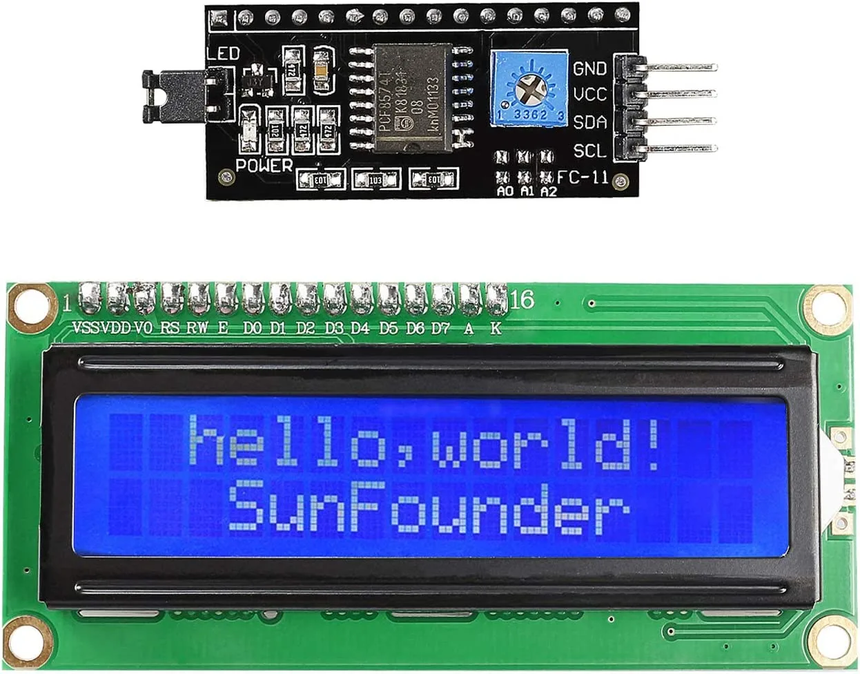
LCD1602係一款好受歡迎嘅字母數字顯示屏,有16行同2列。標準嘅並行LCD需要好多數碼引腳嚟控制。不過,呢款顯示屏背面裝咗一個專用嘅I2C模組(喺影片01:30)。呢個模組大幅簡化咗接線,將連接減少到只需四條線:VCC、GND、SDA同SCL。之所以可以咁做,係因為I2C模組充當橋樑,將簡單嘅I2C串行信號轉換成LCD需要嘅並行信號。
呢個項目使用I2C接口,呢個係一種通訊協議,容許你嘅Arduino只用兩條線就可以同多個設備通訊。呢個係連接好多類型感應器同顯示屏嘅基本技能。
接線指南
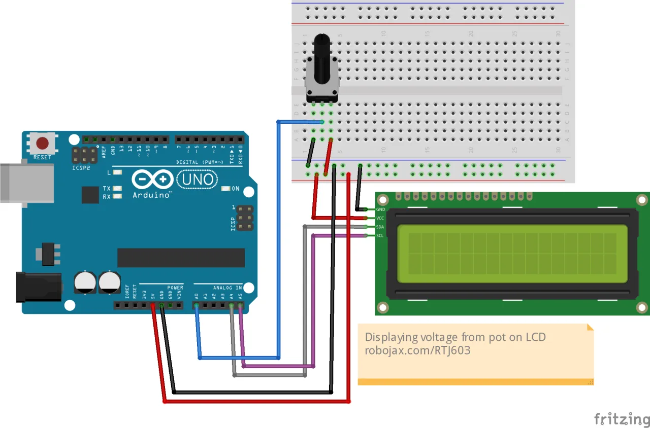
將LCD同可變電阻器連接到Arduino好簡單。I2C模組需要電源同兩條通訊線。可變電阻器充當可變電壓分壓器,容許你調整佢滑臂引腳嘅電壓。
以下係詳細嘅接線設置:
- LCD I2C模組到Arduino:
- GND 連到Arduino嘅 GND(喺影片05:38)。
- VCC 連到Arduino嘅 5V(喺影片05:47)。
- SDA 連到Arduino嘅 A4(喺影片05:47)。
- SCL 連到Arduino嘅 A5(喺影片05:57)。
- 可變電阻器到Arduino:
- 左邊引腳 連到Arduino嘅 5V(喺影片33:39)。
- 中間引腳(滑臂) 連到Arduino嘅 A0(喺影片33:43)。
- 右邊引腳 連到Arduino嘅 GND(喺影片33:43)。
安裝所需函式庫
呢個項目需要一個外部函式庫嚟通過I2C控制LCD。影片中使用嘅函式庫係「Arduino Liquid Crystal I2C」函式庫。你可以從Robojax資源頁面或者GitHub上提供嘅連結下載佢(喺影片06:16)。
要安裝佢,先將函式庫下載做ZIP檔案。然後,喺你嘅Arduino IDE入面,去Sketch > Include Library > Add .ZIP Library...,然後選擇下載嘅檔案(喺影片06:41)。
搵你LCD嘅I2C地址
喺上傳主程式碼之前,好重要嘅一步係確定你特定LCD模組嘅I2C地址。呢個地址可能因製造商而異。影片示範咗點樣用I2C掃描器嚟搵佢(喺影片08:11)。
你可以去File > Examples > Wire > i2c_scanner搵到呢個掃描器。將呢段程式碼上傳到連接咗LCD嘅Arduino,然後打開串行監視器。佢會顯示地址,通常係0x27或者0x3F。你需要喺主程式碼入面用呢個地址。
程式碼解釋
呢個項目嘅程式碼集中喺讀取模擬數值同格式化顯示。等我哋拆解吓關鍵嘅、用戶可配置嘅部分。
1. 函式庫包含同LCD物件
呢個部分包含所需嘅函式庫,並為你嘅LCD創建一個物件。呢度最重要嘅部分係I2C地址,你一定要將佢改成上一步搵到嘅地址。
#include <Wire.h>
#include <LiquidCrystal_I2C.h>

// 將LCD地址設為0x27,適用於16或20字符同2或4行顯示
LiquidCrystal_I2C lcd(0x27, 16, 2);
#include <Wire.h>:呢個庫係Arduino內置嘅,係I2C通訊所必需嘅。#include <LiquidCrystal_I2C.h>:呢個包含咗我哋啱啱安裝嘅庫,佢提供控制LCD嘅函數。LiquidCrystal_I2C lcd(0x27, 16, 2);:呢行建立一個名為lcd嘅物件。第一個參數0x27係你之前搵到嘅I2C地址。第二同第三個參數定義LCD嘅尺寸:16列同2行。 如果地址唔同,你一定要將0x27改做你嘅特定地址。
2. 設定同循環函數
setup()函數初始化LCD並打開背光。loop()函數包含讀取電壓同顯示嘅核心邏輯。
void setup()
{
  lcd.begin();
  lcd.backlight();
}

void loop()
{
  int potValue = analogRead(A0);
  float voltage = potValue * (5.0 / 1023.0);
  // ... (LCD顯示代碼)
  delay(1000);
}lcd.begin():呢個初始化LCD接口並準備好俾佢使用。lcd.backlight():呢個打開顯示器嘅背光,令文字可見。int potValue = analogRead(A0);:呢個讀取A0引腳嘅原始模擬值,A0連接住電位器嘅滑動臂。個值會係0到1023之間嘅整數,代表0V到5V嘅電壓。float voltage = potValue * (5.0 / 1023.0);:呢個係關鍵嘅轉換步驟。佢將原始ADC值轉換成實際電壓讀數。公式將原始值乘以參考電壓(5.0V)同最大ADC值(1023)嘅比例。呢個係必要嘅,因為ADC唔係直接讀電壓;佢讀嘅係一個成比例嘅數字。
3. 顯示電壓
代碼跟住清除屏幕,並喺第二行嘅特定位置打印電壓值。
  lcd.clear();
  lcd.print("LCD1602 Tutorial");
  lcd.setCursor (0,1); // 去第二行開頭
  lcd.print("Voltage:");
  lcd.setCursor (9,1); // 設定去第二行第9個字符
  lcd.print(voltage);
  lcd.setCursor (13,1); // 設定去第二行第14個字符
lcd.print("V"); lcd.clear():清除屏幕上之前嘅任何文字。lcd.print("LCD1602 Tutorial"):喺第一行打印標題。lcd.setCursor (0,1):將光標設定去第二行嘅開頭。第一個參數係列(0-15),第二個係行(0係第一行,1係第二行)。lcd.print(voltage):打印計算出嚟嘅電壓值。float變量預設會打印兩位小數。lcd.setCursor (13,1):將光標移去第二行第13列,將「V」字符放喺數字後面。
現場項目示範
一旦你上傳咗代碼,LCD應該會喺第一行顯示「LCD1602 Tutorial」。喺第二行,佢會顯示「Voltage:」後面跟住當前電壓讀數。當你轉動電位器嘅旋鈕,你會見到顯示嘅電壓實時變化,範圍大約由0.00V到5.00V(喺影片35:25位置)。
呢個項目係一個完美嘅例子,示範點樣將原始模擬信號轉換成清晰、人類可讀嘅值。你喺度學到嘅技能可以直接應用喺將來可能用到嘅任何其他模擬傳感器上。
影片仲涵蓋其他相關主題,例如喺LCD上顯示文字、滾動同建立自訂字符。
呢條影片嘅相關項目
章節
- [00:00] LCD1602介紹同項目概覽
- [01:30] LCD1602硬件同I2C模組解釋
- [04:06] 用跳線設定I2C地址
- [05:28] LCD1602嘅接線圖
- [07:31] 基本文字顯示嘅代碼解釋
- [11:10] 示範閃爍光標例子
- [13:46] 建立同使用自訂字符
- [18:51] 使用串行顯示例子
- [23:16] 喺LCD上滾動文字
- [26:13] 顯示DHT11嘅溫度同濕度
- [33:00] 讀取同顯示電位器嘅電壓
- [35:56] 顯示超聲波傳感器嘅距離
圖片
/*
Lesson 20/31: Displaying voltage on LCD1602
Get this code and watch video Download and resource page https://robojax.com/RJT603
YouTube video https://www.youtube.com/watch?v=NXAswOc_2zg


 * This code is "AS IS" without warranty or liability. Free to be used as long as you keep this note intact.*
 * This code has been download from Robojax.com
    This program is free software: you can redistribute it and/or modify
    it under the terms of the GNU General Public License as published by
    the Free Software Foundation, either version 3 of the License, or
    (at your option) any later version.

    This program is distributed in the hope that it will be useful,
    but WITHOUT ANY WARRANTY; without even the implied warranty of
    MERCHANTABILITY or FITNESS FOR A PARTICULAR PURPOSE.  See the
    GNU General Public License for more details.

    You should have received a copy of the GNU General Public License
    along with this program.  If not, see <https://www.gnu.org/licenses/>.
 */
#include <Wire.h>
#include <LiquidCrystal_I2C.h>

// Set the LCD address to 0x27 for a 16 or 20 chars and 2 or 4 lines display
LiquidCrystal_I2C lcd(0x27, 16, 2);

int count =700;
void setup()
{
  // Robojax code for LCD with I2C
	// initialize the LCD,
	lcd.begin();

	// Turn on the blacklight and print a message.
	lcd.backlight();
  // Robojax code for LCD with I2C


}

void loop()
{
  int potValue = analogRead(A0);
  float voltage = potValue * (5.0 / 1023.0);
  //start of loop Robojax code for LCD with I2C
  lcd.clear();
  lcd.print("LCD1602 Tutorial");
  lcd.setCursor (0,1); // go to start of 2nd line
  lcd.print("Voltage:");

  lcd.setCursor (9,1); // set to line 2 char 9
  lcd.print(voltage);

  lcd.setCursor (13,1); // set to line 2 char 14
  lcd.print("V");

  //lcd.setCursor (3,3); // set to line 4 character 4
  //lcd.print("Text in line 4");

  delay(1000);
  count++;
 //end of loopcode Robojax code for LCD with I2C
}
你可能需要嘅嘢
-
亞馬遜SunFounder Arduino Learning Kit on AliExpresss.click.aliexpress.com
-
亞馬遜
-
亞馬遜
-
亞馬遜
資源與參考資料
-
文件记录Documentation for SunFounder 3 in 1 IoT/Smart Car/Learning Kitdocs.sunfounder.com
-
外部Purchase SunFounder's 3-in-1 Smart car learning kitsunfounder.com
文件📁
Arduino 函式庫 (zip)
-
SunFounder's 3-in-1 Smart Car learning kit source code
3in1-kit-main-v2.zip12.80 MB
用户手册
-
SunFounder 3-in-1 Arduino Smart Car assembly manualThis document shows step by step assembly of SunFounder 3-in-1 Arduino Smart Car
SunFounder_car_assembly_manual.pdf1.20 MB


![Arduino Starter Kit R4 [K000007_R4] – Learn Electronics and Coding with the UNO R4 WiFi Board, 13 Guided Projects in a Printed Book + Growing Resources Online, Official Certification Voucher](https://m.media-amazon.com/images/I/51mjbAi4hGL._SL75_.jpg)