Lesson 20/31: Displaying voltage on LCD1602
This project demonstrates how to build a digital voltmeter using an Arduino and an LCD1602 display with an I2C interface. By reading the analog voltage from a potentiometer and displaying it on the screen, you'll learn the essential skills of analog-to-digital conversion, I2C communication, and LCD control.
This project is a great stepping stone for many practical applications. Here are some ideas you can build upon:
- Building a portable battery voltage monitor for your projects.
- Creating a simple power supply with a visual voltage readout.
- Monitoring the output of a solar panel or other variable voltage source.
- Displaying the value from any analog sensor, like a light-dependent resistor (LDR), as a readable number.
By the end of this guide, you will have a clear understanding of how to connect the components, configure the necessary libraries, and write the code to create your own voltage display.

Hardware Components
To build this project, you will need the following components. The course is based on the SunFounder 3-in-1 Arduino kit, which includes all of these parts.
- Arduino Board (e.g., Uno)
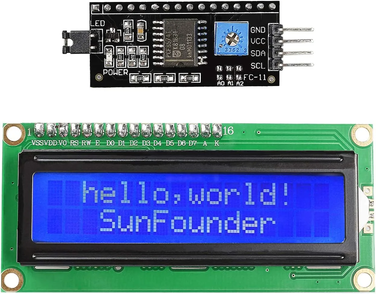
- LCD1602 Display with I2C module
- Potentiometer (10kΩ recommended)
- Jumper Wires
- Breadboard
Understanding the LCD1602 and I2C Module
The LCD1602 is a popular alphanumeric display with 16 columns and 2 rows. A standard parallel LCD would require many digital pins to control. However, this display comes with a dedicated I2C module attached to its back (in video at 01:30). This module simplifies the wiring dramatically, reducing the connection to just four wires: VCC, GND, SDA, and SCL. This is possible because the I2C module acts as a bridge, translating the simple I2C serial signal into the parallel signals the LCD needs.
This project uses the I2C interface, which is a communication protocol that allows your Arduino to talk to multiple devices using just two wires. This is a fundamental skill for connecting many types of sensors and displays.
Wiring Guide
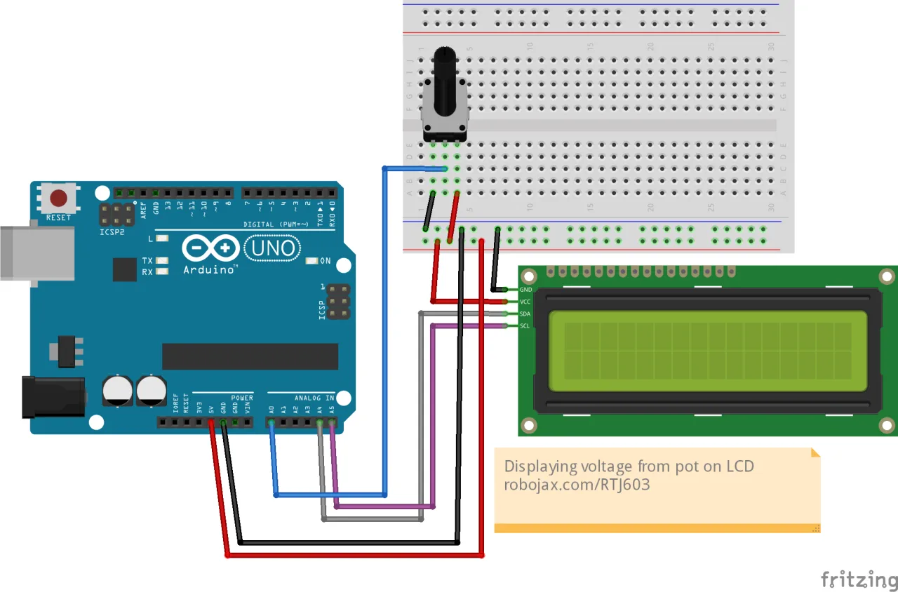
Connecting the LCD and the potentiometer to the Arduino is straightforward. The I2C module needs power and two communication lines. The potentiometer acts as a variable voltage divider, allowing you to adjust the voltage at its wiper pin.
Here's the detailed wiring setup:
- LCD I2C Module to Arduino:
- GND to Arduino GND (in video at 05:38).
- VCC to Arduino 5V (in video at 05:47).
- SDA to Arduino A4 (in video at 05:47).
- SCL to Arduino A5 (in video at 05:57).
- Potentiometer to Arduino:
- Left Pin to Arduino 5V (in video at 33:39).
- Middle Pin (Wiper) to Arduino A0 (in video at 33:43).
- Right Pin to Arduino GND (in video at 33:43).
Installing the Required Library
This project requires an external library to control the LCD over I2C. The library used in the video is the "Arduino Liquid Crystal I2C" library. You can download it from the link provided on the Robojax resource page or from GitHub (in video at 06:16).
To install it, download the library as a ZIP file. Then, in your Arduino IDE, go to Sketch > Include Library > Add .ZIP Library... and select the downloaded file (in video at 06:41).
Finding Your LCD's I2C Address
Before uploading the main code, it's crucial to determine the I2C address of your specific LCD module. This address can vary depending on the manufacturer. The video demonstrates how to use an I2C scanner to find it (in video at 08:11).
You can find this scanner by going to File > Examples > Wire > i2c_scanner. Upload this code to your Arduino with the LCD connected, and open the Serial Monitor. It will display the address, which is often 0x27 or 0x3F. You will need to use this address in your main code.
Code Explanation
The code for this project is focused on reading an analog value and formatting it for display. Let's break down the key, user-configurable parts.
1. Library Inclusions and LCD Object
This section includes the necessary libraries and creates an object for your LCD. The most important part here is the I2C address, which you must change to match the one you found in the previous step.
#include <Wire.h>
#include <LiquidCrystal_I2C.h>

// Set the LCD address to 0x27 for a 16 or 20 chars and 2 or 4 lines display
LiquidCrystal_I2C lcd(0x27, 16, 2);
#include <Wire.h>: This library is built into Arduino and is required for I2C communication.#include <LiquidCrystal_I2C.h>: This includes the library we just installed, which provides the functions to control the LCD.LiquidCrystal_I2C lcd(0x27, 16, 2);: This line creates an object namedlcd. The first parameter,0x27, is the I2C address you found earlier. The second and third parameters define the LCD's dimensions: 16 columns and 2 rows. You must change0x27to your specific address if it's different.
2. Setup and Loop Functions
The setup() function initializes the LCD and turns on its backlight. The loop() function contains the core logic for reading the voltage and displaying it.
void setup()
{
  lcd.begin();
  lcd.backlight();
}

void loop()
{
  int potValue = analogRead(A0);
  float voltage = potValue * (5.0 / 1023.0);
  // ... (LCD display code)
  delay(1000);
}lcd.begin(): This initializes the LCD interface and prepares it for use.lcd.backlight(): This turns on the display's backlight, making the text visible.int potValue = analogRead(A0);: This reads the raw analog value from pin A0, which is connected to the potentiometer's wiper. The value will be an integer between 0 and 1023, representing the voltage from 0V to 5V.float voltage = potValue * (5.0 / 1023.0);: This is the crucial conversion step. It converts the raw ADC value into an actual voltage reading. The formula multiplies the raw value by the ratio of the reference voltage (5.0V) to the maximum ADC value (1023). This is necessary because the ADC doesn't read voltage directly; it reads a proportional number.
3. Displaying the Voltage
The code then clears the screen and prints the voltage value at a specific position on the second line.
  lcd.clear();
  lcd.print("LCD1602 Tutorial");
  lcd.setCursor (0,1); // go to start of 2nd line
  lcd.print("Voltage:");
  lcd.setCursor (9,1); // set to line 2 char 9
  lcd.print(voltage);
  lcd.setCursor (13,1); // set to line 2 char 14
lcd.print("V"); lcd.clear(): Clears any previous text from the screen.lcd.print("LCD1602 Tutorial"): Prints the title on the first line.lcd.setCursor (0,1): Sets the cursor to the start of the second line. The first parameter is the column (0-15), and the second is the row (0 for the first line, 1 for the second).lcd.print(voltage): Prints the calculated voltage value. Thefloatvariable will be printed with two decimal places by default.lcd.setCursor (13,1): Moves the cursor to column 13 on the second line to position the "V" character right after the number.
Live Project Demonstration
Once you have uploaded the code, the LCD should display "LCD1602 Tutorial" on the first line. On the second line, it will show "Voltage:" followed by the current voltage reading. As you rotate the potentiometer's knob, you will see the displayed voltage change in real-time, ranging from approximately 0.00V to 5.00V (in video at 35:25).
This project is a perfect example of how to take a raw analog signal and turn it into a clear, human-readable value. The skills you've learned here can be directly applied to any other analog sensor you might use in the future.
The video also covers other related topics, such as displaying text, scrolling, and creating custom characters on the LCD.
Related projects from this video
- Lesson 20/31: Using LCD1602 with Arduino display text | Robojax
- Lesson 20/31: Displaying Temperature and humidity from DHT11 on LCD screen
Chapters
- [00:00] Introduction to the LCD1602 and project overview
- [01:30] LCD1602 hardware and I2C module explanation
- [04:06] Setting the I2C address with jumpers
- [05:28] Wiring diagram for the LCD1602
- [07:31] Code explanation for basic text display
- [11:10] Demonstrating the blinking cursor example
- [13:46] Creating and using custom characters
- [18:51] Using the serial display example
- [23:16] Scrolling text on the LCD
- [26:13] Displaying temperature and humidity from DHT11
- [33:00] Reading and displaying voltage from a potentiometer
- [35:56] Displaying distance from an ultrasonic sensor
Images
/*
Lesson 20/31: Displaying voltage on LCD1602
Get this code and watch video Download and resource page https://robojax.com/RJT603
YouTube video https://www.youtube.com/watch?v=NXAswOc_2zg


 * This code is "AS IS" without warranty or liability. Free to be used as long as you keep this note intact.*
 * This code has been download from Robojax.com
    This program is free software: you can redistribute it and/or modify
    it under the terms of the GNU General Public License as published by
    the Free Software Foundation, either version 3 of the License, or
    (at your option) any later version.

    This program is distributed in the hope that it will be useful,
    but WITHOUT ANY WARRANTY; without even the implied warranty of
    MERCHANTABILITY or FITNESS FOR A PARTICULAR PURPOSE.  See the
    GNU General Public License for more details.

    You should have received a copy of the GNU General Public License
    along with this program.  If not, see <https://www.gnu.org/licenses/>.
 */
#include <Wire.h>
#include <LiquidCrystal_I2C.h>

// Set the LCD address to 0x27 for a 16 or 20 chars and 2 or 4 lines display
LiquidCrystal_I2C lcd(0x27, 16, 2);

int count =700;
void setup()
{
  // Robojax code for LCD with I2C
	// initialize the LCD,
	lcd.begin();

	// Turn on the blacklight and print a message.
	lcd.backlight();
  // Robojax code for LCD with I2C


}

void loop()
{
  int potValue = analogRead(A0);
  float voltage = potValue * (5.0 / 1023.0);
  //start of loop Robojax code for LCD with I2C
  lcd.clear();
  lcd.print("LCD1602 Tutorial");
  lcd.setCursor (0,1); // go to start of 2nd line
  lcd.print("Voltage:");

  lcd.setCursor (9,1); // set to line 2 char 9
  lcd.print(voltage);

  lcd.setCursor (13,1); // set to line 2 char 14
  lcd.print("V");

  //lcd.setCursor (3,3); // set to line 4 character 4
  //lcd.print("Text in line 4");

  delay(1000);
  count++;
 //end of loopcode Robojax code for LCD with I2C
}
Things you might need
-
AmazonSunFounder Arduino Learning Kit on AliExpresss.click.aliexpress.com
-
Amazon
-
Amazon
-
Amazon
-
Amazon
Resources & references
-
DocumentationDocumentation for SunFounder 3 in 1 IoT/Smart Car/Learning Kitdocs.sunfounder.com
-
ExternalPurchase SunFounder's 3-in-1 Smart car learning kitsunfounder.com
Files📁
Arduino Libraries (zip)
-
SunFounder's 3-in-1 Smart Car learning kit source code
3in1-kit-main-v2.zip12.80 MB
User’s Manual
-
SunFounder 3-in-1 Arduino Smart Car assembly manualThis document shows step by step assembly of SunFounder 3-in-1 Arduino Smart Car
SunFounder_car_assembly_manual.pdf1.20 MB


![Arduino Starter Kit R4 [K000007_R4] – Learn Electronics and Coding with the UNO R4 WiFi Board, 13 Guided Projects in a Printed Book + Growing Resources Online, Official Certification Voucher](https://m.media-amazon.com/images/I/51mjbAi4hGL._SL75_.jpg)