این آموزش بخشی است از: کنترل رله با استفاده از آردوینو
این یک گروه از ویدیوهای مربوط به رله است. لینک سایر ویدیوها در زیر این مقاله قرار دارد.

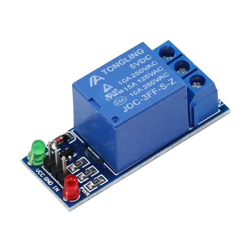
استفاده از ماجیول ریلی ۵ ولت (کم-تحریک) با آردوینو
در این آموزش، بررسی خواهیم کرد که چگونه یک ماجیول ریلی ۵ ولتی را با آردوینو استفاده کنیم و بهطور خاص بر روی یک ریلی با تحریک پایین تمرکز خواهیم کرد. ریلی این امکان را به شما میدهد که دستگاههای با ولتاژ بالا را با یک میکروکنترلر با ولتاژ پایین کنترل کنید و این امر آن را به یک جزء ضروری برای پروژههای مختلف اتوماسیون تبدیل میکند. در پایان این آموزش، قادر خواهید بود که یک ریلی را با استفاده از آردوینو روشن و خاموش کنید، که میتوان از آن برای کنترل چراغها، موتورها و سایر دستگاهها استفاده کرد.
برای دستیابی به این هدف، برنامه سادهای برای آردوینو خواهیم نوشت که ریلی را در فواصل منظم روشن و خاموش کند. این پروژه ساده و مناسب برای مبتدیانی است که میخواهند درک کنند ریلیها چگونه با میکروکنترلرها کار میکنند (در ویدیو در دقیقه ۰۰:۳۰).
بار قدرت بارگذاری
قدرت نامی ریلی 5 ولتی شما که برای 10 آمپر برچسبگذاری شده است، نه توسط ولتاژ سیمپیچ خود بلکه توسط حداکثر جریانی که میتواند به طور ایمن برای بار (دستگاهی) که کنترل میکنید، قطع و وصل کند تعیین میشود. "5 ولت" به ولتاژی که برایبهرهوری مغناطیسی سیمپیچ ریلی را افزایش دهید، در حالی که "10A" آن استرتبه تماسحداکثر جریانی که کلید داخلی میتواند تحمل کند. برای محاسبه حداکثر توان بار (به وات) که ریلی میتواند وصل یا قطع کند، باید مقدار جریان ریلی (10A) را در ولتاژ مدار که در حال سوئیچ کردن هستید ضرب کنید. به عنوان مثال، سوئیچ کردن یک دستگاه 100V AC: 10A × 100V = 1000W. برای یک لوازم جانبی 12V DC خودرو: 10A × 12V = 120W.بهطور حیاتی، شما باید همیشه اطمینان حاصل کنید که ولتاژ مدار که آن را تغییر میدهید از حداکثر ولتاژ تماس مشخص شده ریلی تجاوز نکند، که یک درجهبندی جداگانه و بالاتر (بهعنوان مثال، 250 ولت AC) در برگه مشخصات آن ذکر شده است.بنابراین، ریلی شما میتواند هر بار باری تا 10 آمپر را کنترل کند، به شرطی که ولتاژ بار در محدوده ولتاژ تماس ریلی باشد و شما توان مربوطه را از آنجا محاسبه کنید.
توضیح سختافزار
اجزای اصلی مورد نیاز برای این پروژه شامل یک برد آردوینو، یک ماجیول ریلی 5 ولتی و سیمهای جامپر است. برد آردوینو به عنوان مغز عملیات عمل کرده و سیگنالها را به ماجیول ریلی ارسال میکند تا وضعیت آن را کنترل کند. ماجیول ریلی به گونهای طراحی شده است که با کنترل سمت ولتاژ بالا با سیگنال ولتاژ پایین از آردوینو، دستگاهها را روشن یا خاموش کند.
هر ماجیول ریلی معمولاً شامل یک ایزولاتور اپتو برای جداسازی بین مدارهای ولتاژ پایین و ولتاژ بالا است که از آردوینو در برابر EMF برگشتی و نوسانات ولتاژ محافظت میکند. در مورد ما، ما از یک ریلی با تریگر پایین استفاده خواهیم کرد، به این معنی که وقتی سیگنال کنترل بر روی LOW تنظیم شود، فعال میشود.


ریلی چیست؟
ریلی یک سویچ الکترومغناطیسی است که از یک جریان الکتریکی کوچک برای کنترل یک جریان بسیار بزرگتر استفاده میکند و بهطور ایمن بخشهای مختلف یک مدار را ایزوله میسازد. همانطور که در نمودارها نشان داده شده است، ریلی دو بخش اصلی دارد:سیم پیچو همچنینمخاطبین. هنگامی که باتری 5 ولتی را از طریق سوئیچ کوچک وصل میکنید، برق از طریق سیمپیچ ریلی جاری میشود. این سیمپیچ را به یک آهنربای الکتریکی تبدیل میکند که بهطور فیزیکی سوئیچ داخلی را میکشد-تماسهابسته شده. این عمل یک مدار جداگانه و پرقدرت را متصل میکند. در واقع، سیگنال کوچک 5 ولتی از باتری و سوئیچ به عنوان یک کنترل از راه دور عمل میکند و به شما اجازه میدهد که از یک مدار امن و با ولتاژ پایین برای روشن و خاموش کردن یک دستگاه پرقدرت و با ولتاژ بالا استفاده کنید بدون اینکه دو جریان هرگز به طور مستقیم با هم ترکیب شوند.
جزئیات مشخصات فنی
| تولید کننده | عمومی |
|---|---|
| شماره قطعه | ماجیول ریلی 5 ولت |
| ولتاژ کنترل | ۵ ولت |
| نوع ریلی | پایین-تحریک |
| ولتاژ بار حداکثر | ۲۵۰ ولت AC / ۳۰ ولت DC |
| جریان بار حداکثر | ۱۰ A |
| جداسازی اپتیکی | بله |
| بسته | مدول |
- هنگام استفاده از بارهای بالا، از حرارتزدایی مناسب اطمینان حاصل کنید.
- برای دستگاههای با ولتاژ بالا از یک منبع تغذیه جداگانه استفاده کنید.
- اتصالات را دوباره بررسی کنید تا از وقوع اتصالات کوتاه جلوگیری شود.
- تأیید کنید که مشخصات ریلی با بار مورد نظر شما مطابقت دارد.
- قبل از اتصال ولتاژ بالا، ریلی را با یک مولتیمتر آزمایش کنید.
دستورالعمل های سیم کشی

برای سیمکشی ماجیول ریلی، ابتدا پایه VCC ماجیول ریلی را به پایه 5V روی آردوینو متصل کنید. سپس پایه GND ماجیول ریلی را به پایه GND آردوینو متصل کنید. پایه کنترل برای ریلی، که معمولاً به عنوان IN برچسبگذاری شده، باید به یک پایه دیجیتال روی آردوینو، به عنوان مثال، پایه 8 متصل شود. این تنظیم به آردوینو اجازه میدهد تا وضعیت ریلی را کنترل کند.
پس از اتمام سیمکشی، شما VCC و GND را برای تأمین برق ماجیول ریلی خواهید داشت، در حالی که پایه کنترل سیگنالهایی برای روشن و خاموش کردن ریلی ارسال خواهد کرد. مطمئن شوید که اتصالات ایمن هستند تا از بروز هرگونه مشکلات مقطعی در حین عملکرد جلوگیری شود. اگر از برد آردوینو دیگری استفاده میکنید، حتماً پایه کنترل را بهطور مناسب نقشهبرداری کنید.
نمونههای شِفر (کود) و راهنمایی
int relayPin = 8; // define output pin for relay

void setup() {
  pinMode(relayPin, OUTPUT); // define pin 8 as output
}

void loop() {
  digitalWrite(relayPin, LOW); // turn the relay ON
  delay(500); // wait for 500 milliseconds
  digitalWrite(relayPin, HIGH); // turn the relay OFF
  delay(500); // wait for 500 milliseconds
}
در شِفر (کود)، ما با تعریف پایه خروجی برای ریلی شروع میکنیم باrelayPinتنظیم شده به ۸. درsetup()این پایه را به عنوان یک خروجی پیکربندی میکنیم.loop()تابع به طور مداوم وضعیت ریلی را با نوشتن LOW در پایه تغییر میدهد، آن را روشن میکند و سپس با نوشتن HIGH، بعد از تأخیری ۵۰۰ میلیثانیهای خاموش میکند.
نمایشگاه / چه انتظاری باید داشته باشیم
پس از اتمام سیمکشی و برنامهنویسی، باید مشاهده کنید که ریلی هر نیم ثانیه یکبار کلیک میکند. این نشاندهنده این است که آردوینو بهخوبی ریلی را کنترل میکند. اگر یک دستگاه با ولتاژ بالا را به ریلی متصل کنید، باید همزمان با وضعیت ریلی روشن و خاموش شود. مطمئن شوید که ریلی برای ولتاژ و جریان دستگاهی که کنترل میکنید، مناسب است تا از آسیب جلوگیری شود (در ویدیو در :15).
اشتباهات رایج شامل سیمکشی نادرست است که میتواند منجر به عملکرد نامناسب ریلی شود. علاوه بر این، اطمینان حاصل کنید که از یک ریلی با تحریک پایین استفاده میکنید؛ در غیر این صورت، ممکن است نیاز باشد شِفر (کود) را برای سازگاری با ریلی با تحریک بالا تنظیم کنید.
برچسبهای زمانی ویدئو
- ۰۰:۰۰معرفی پروژه
- ۰۰:۳۰نمای کلی سختافزار
- ۰۱:۱۵دستورالعملهای سیمکشی
- ۰۲:۱۵نمایش عملکرد ریلی
تصاویر

این آموزش بخشی از: کنترل رله با استفاده از آردوینو
- Arduino Code and Video for a Dual-Channel 5V Relay
- کنترل ریلی 5V با استفاده از آردوینو برای راهاندازی بار AC یا DC مانند لامپ یا موتور
- TTP224 حساس(حس کننده) لمسی 4 کاناله برای قطع و وصل بارهای AC/DC با ریلی
- استفاده از ماجیول MAX6675 برای ترموکوپل نوع K همراه با ریلی و نمایشگر
- استفاده از سوئیچ رید برای کنترل ریلی و بارهای AC/DC با آردوینو
- استفاده از ماجیول لمسی TTP223B و ریلی برای کنترل بارهای AC/DC با آردوینو
- استفاده از یک دکمه فشاری آردوینو برای قطع و وصل کردن ریلی و لامپ AC
This code has not been parsed yet. Please return to the admin panel to parse it.منابع و مراجع
هنوز هیچ منبعی موجود نیست.
فایلها📁
فایل فریزینگ
-
ماجیول ریلی 5 ولت_تحریک پایین
5V Relay Module_LOW_trigger.fzpz0.08 MB -
ریلی 5 ولت 2.0
5V RELAY 2.0.fzpz0.02 MB


![Arduino Uno REV3 [A000066] - ATmega328P Microcontroller, 16MHz, 14 Digital I/O Pins, 6 Analog Inputs, 32KB Flash, USB Connectivity, Compatible with Arduino IDE for DIY Projects and Prototyping](https://m.media-amazon.com/images/I/515P6aYSP4L._SL75_.jpg)


![Arduino Starter Kit R4 [K000007_R4] – Learn Electronics and Coding with The UNO R4 WiFi Board, 13 Guided Projects in a Printed Book + Growing Resources Online, Official Certification Voucher](https://m.media-amazon.com/images/I/51mjbAi4hGL._SL75_.jpg)