How to Control the Speed of a DC Motor with an ESP32 and L298N Module
Controlling DC motors can be a straightforward task with the right components and understanding. In this tutorial, we will explore how to control two DC motors using the ESP32 microcontroller and the L298N motor driver module. By the end of this guide, you will be able to adjust the speed and direction of your motors based on PWM signals from the ESP32, allowing for versatile applications in robotics and automation.
The video accompanying this tutorial provides a visual demonstration of the entire process, including wiring and coding (in video at 00:00).
Hardware Explained

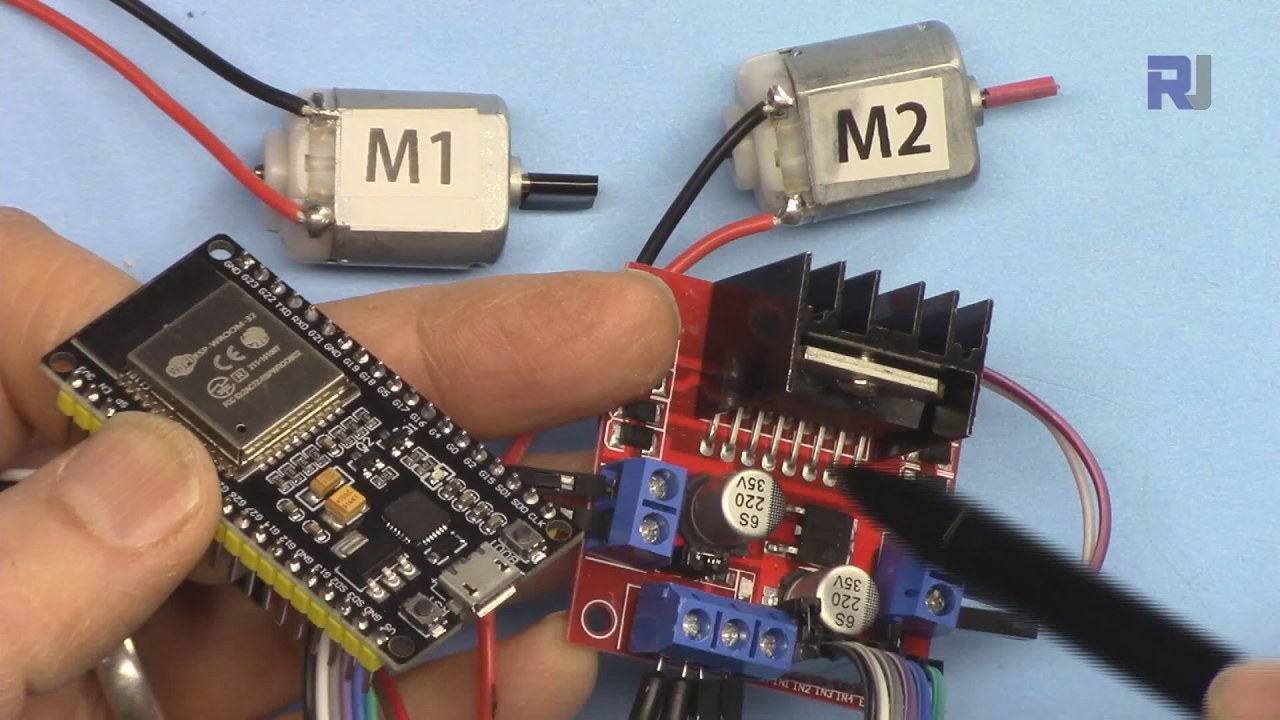
To achieve motor control, we will be using the ESP32 and the L298N motor driver module. The ESP32 is a powerful microcontroller with Wi-Fi and Bluetooth capabilities, making it ideal for IoT projects. The L298N is an H-bridge motor driver that allows us to control the direction and speed of the motors by using PWM signals. The L298N module features two H-bridge circuits, which means we can control two motors independently. Each H-bridge allows for control over the direction of the motor (clockwise or counterclockwise) and the speed by varying the PWM signal. By connecting the enable and input pins of the L298N to the ESP32, we can manipulate the motors effectively.
Datasheet Details
| Manufacturer | STMicroelectronics |
|---|---|
| Part number | L298N |
| Logic/IO voltage | 5 V |
| Supply voltage | 5–46 V (VS) |
| Output current (per channel) | 2 A max/channel (abs. max) |
| Peak current (per channel) | 2.5 A |
| PWM frequency guidance | 1 kHz - 15 kHz |
| Input logic thresholds | 2.5 V (high), 1.5 V (low) |
| Voltage drop / RDS(on) / saturation | 1.8 V at 2 A |
| Thermal limits | 150 °C |
| Package | 15-pin Multiwatt |
| Notes / variants | Dual H-bridge motor driver |
- Ensure the motor's voltage rating matches the L298N's supply voltage.
- Use adequate heat sinking for continuous operation at high currents.
- Connect grounds of all components to avoid floating references.
- Use a PWM frequency suitable for the application (1-15 kHz).
- Be cautious of maximum current ratings to prevent overheating.
- Test motor direction before finalizing wiring to avoid damage.
- Consider decoupling capacitors on the power supply for stability.
Wiring Instructions

To wire the L298N to the ESP32, start by connecting the two DC motors to the output terminals of the L298N. Connect Motor 1 to the terminals labeled as OUT1 and OUT2, and Motor 2 to OUT3 and OUT4. The polarity of the motors does not matter as the L298N will handle the direction. Next, connect your external power supply to the VMS and GND terminals on the L298N. Ensure that the voltage is appropriate for your motors, typically between 5V and 46V. The 5V terminal on the L298N can be used to power the ESP32 if needed, but ensure the current requirements are met. For the control pins, connect ENA to GPIO 19, IN1 to GPIO 18, and IN2 to GPIO 5 for Motor 1. For Motor 2, connect IN3 to GPIO 17, IN4 to GPIO 16, and ENB to GPIO 4. Finally, connect the grounds of the ESP32 and L298N together to ensure a common reference.
Code Examples & Walkthrough
The following code snippets illustrate how to control the motors using the L298N library designed for the ESP32. The library simplifies the process of sending commands to the motors. First, the necessary library is included, and motor parameters are defined:
#include
#define ENA 19
#define IN1 18
#define IN2 5
#define IN3 17
#define IN4 16
#define ENB 4
Robojax_L298N_DC_motor robot(IN1, IN2, ENA, CHA, IN3, IN4, ENB, CHB);
In this snippet, we define the control pins for both motors. The library instance robot is created, which will be used to control the motors throughout the program. Next, we set up the serial communication and initialize the robot instance in the setup() function:
void setup() {
  Serial.begin(115200);
  robot.begin();
}
This initializes the serial communication for debugging and prepares the motor control library for operation. Finally, the main control logic is placed in the loop() function, where we can rotate the motors and adjust their speed:
void loop() {
  robot.rotate(motor1, 80, CW); // run motor1 at 80% speed in CW direction
  delay(3000); // wait for 3 seconds
  robot.brake(1); // brake motor1
  delay(2000); // wait for 2 seconds
}
This excerpt demonstrates how to rotate Motor 1 at 80% speed in a clockwise direction for three seconds before braking. The full code includes additional logic for Motor 2 and varying speeds, which can be seen in the complete program loaded below the article.
Demonstration / What to Expect
When executed, the motors should respond to the PWM signals sent from the ESP32. You will see Motor 1 rotating clockwise at 80% speed, followed by a brake action. The program also includes logic to manage speed variations gradually, which can be tested by observing the motor's acceleration from 0% to 100% (in video at 05:00). Common pitfalls include not connecting grounds properly, which can lead to erratic behavior, and exceeding the current ratings of the L298N, causing it to overheat. Make sure to monitor the motor's behavior and adjust parameters as necessary.
Video Timestamps
- 00:46 Introduction
- 04:07 Wiring ESP32 with L298N
- 06:10 Preparing Arduino IDE to work with ESP32 boards
- 08:15 Arduino Code explained
- 15:00 Demonstration of single motor control
- 16:00 Demonstration of controlling 2 DC motors
- 17:00 Demonstration of Powering of ESP32 from L298N and external power
Изображения
/*
 * Library Example for L298N Module to control DC motors
 *
 * This code is to control a single motor. For two motor control, please open L298N_DC_2_Motors.
 * This code is ready for ESP32.
 * Watch video instructions for this code:  https://youtu.be/2JTMqURJTwg
 *
 * Written by Ahmad Shamshiri on December 24, 2019
 * in Ajax, Ontario, Canada. www.robojax.com
 *
 *
  *
 * Get this code and other Arduino codes from Robojax.com.

or make a donation using PayPal http://robojax.com/L/?id=64

 *  * This code is "AS IS" without warranty or liability. Free to be used as long as you keep this note intact.*
 * This code has been downloaded from Robojax.com
    This program is free software: you can redistribute it and/or modify
    it under the terms of the GNU General Public License as published by
    the Free Software Foundation, either version 3 of the License, or
    (at your option) any later version.

    This program is distributed in the hope that it will be useful,
    but WITHOUT ANY WARRANTY; without even the implied warranty of
    MERCHANTABILITY or FITNESS FOR A PARTICULAR PURPOSE.  See the
    GNU General Public License for more details.

    You should have received a copy of the GNU General Public License
    along with this program.  If not, see <https://www.gnu.org/licenses/>.
 */

#include <Robojax_L298N_DC_motor.h>
// motor 1 settings
#define CHA 0
#define ENA 19 // this pin must be PWM enabled pin if Arduino board is used
#define IN1 18
#define IN2 5

// motor 2 settings
#define IN3 17
#define IN4 16
#define ENB 4// this pin must be PWM enabled pin if Arduino board is used
#define CHB 1

const int CCW = 2; // do not change
const int CW  = 1; // do not change

#define motor1 1 // do not change
#define motor2 2 // do not change

// for single motor
//Robojax_L298N_DC_motor robot(IN1, IN2, ENA, CHA, true);

// for two motors without debug information	// Watch video instruction for this line: https://youtu.be/2JTMqURJTwg
Robojax_L298N_DC_motor robot(IN1, IN2, ENA, CHA,  IN3, IN4, ENB, CHB);

// for two motors with debug information
//Robojax_L298N_DC_motor robot(IN1, IN2, ENA, CHA, IN3, IN4, ENB, CHB, true);

void setup() {
  Serial.begin(115200);
  robot.begin();
  //L298N DC Motor by Robojax.com

}

void loop() {

 // robot.demo(1);
  robot.rotate(motor1, 80, CW);//run motor1 at 60% speed in CW direction
  robot.rotate(motor2, 70, CCW);//run motor1 at 60% speed in CW direction

  delay(3000);

  robot.brake(1);
  robot.brake(2);
  delay(2000);


  robot.rotate(motor1, 100, CW);//run motor1 at 60% speed in CW direction
  delay(3000);

  robot.rotate(motor2, 100, CCW);//run motor1 at 60% speed in CW direction

  robot.brake(1);
  robot.brake(2);
  delay(2000);

  for(int i=0; i<=100; i++)
  {
    robot.rotate(motor1, i, CW);// turn motor1 with i% speed in CW direction (whatever is i)
    delay(100);
  }
  delay(2000);

  robot.brake(1);
  delay(2000);

  for(int i=0; i<=100; i++)
  {
    robot.rotate(motor2, i, CW);// turn motor1 with i% speed in CW direction (whatever is i)
    delay(100);
  }
  delay(2000);

  robot.brake(2);
  delay(2000);
  // Robojax L298N Library. Watch video instruction https://youtu.be/2JTMqURJTwg
}
Вещи, которые могут вам понадобиться
-
Амазонка
-
eBay
Ресурсы и ссылки
-
Внешний
Файлы📁
Библиотеки Arduino (zip)
-
robojax_ESP32_L298N_библиотека
robojax_ESP32_L298N_library.zip0.18 MB
Файл Fritzing
-
ESP32-38Pin_Широкий
ESP32-38Pin_Wide.fzpz0.03 MB -
Драйвер постоянного тока L298N
L298N DC motor driver.fzpz0.11 MB