این آموزش بخشی است از: کنترل رله با استفاده از آردوینو
این یک گروه از ویدیوهای مربوط به رله است. لینک سایر ویدیوها در زیر این مقاله قرار دارد.

استفاده از یک دکمه فشاری آردوینو برای قطع و وصل کردن ریلی و لامپ AC
در این آموزش خواهیم آموخت چگونه یک لامپ AC یا چراغ LED را با استفاده از یک دکمه فشاری و یک ریلی کنترل کنیم. دکمه فشاری چراغ را بین حالت روشن و خاموش جابجا میکند و حتی پس از رها شدن دکمه، وضعیت را حفظ میکند. این تنظیم نه تنها کاربردی است بلکه مقدمهای عالی برای کار با ریلیها و بارهای AC نیز محسوب میشود.

در ادامه، قطعات لازم، دستورالعملهای سیمکشی و شِفر (کود) آردوینو که این پروژه را ممکن میسازد را پوشش خواهیم داد. حتماً ویدیوی مرتبط را برای راهنمای تصویری و توضیحات مفصل تماشا کنید (در ویدیو در 00:00).

شرح سختافزار
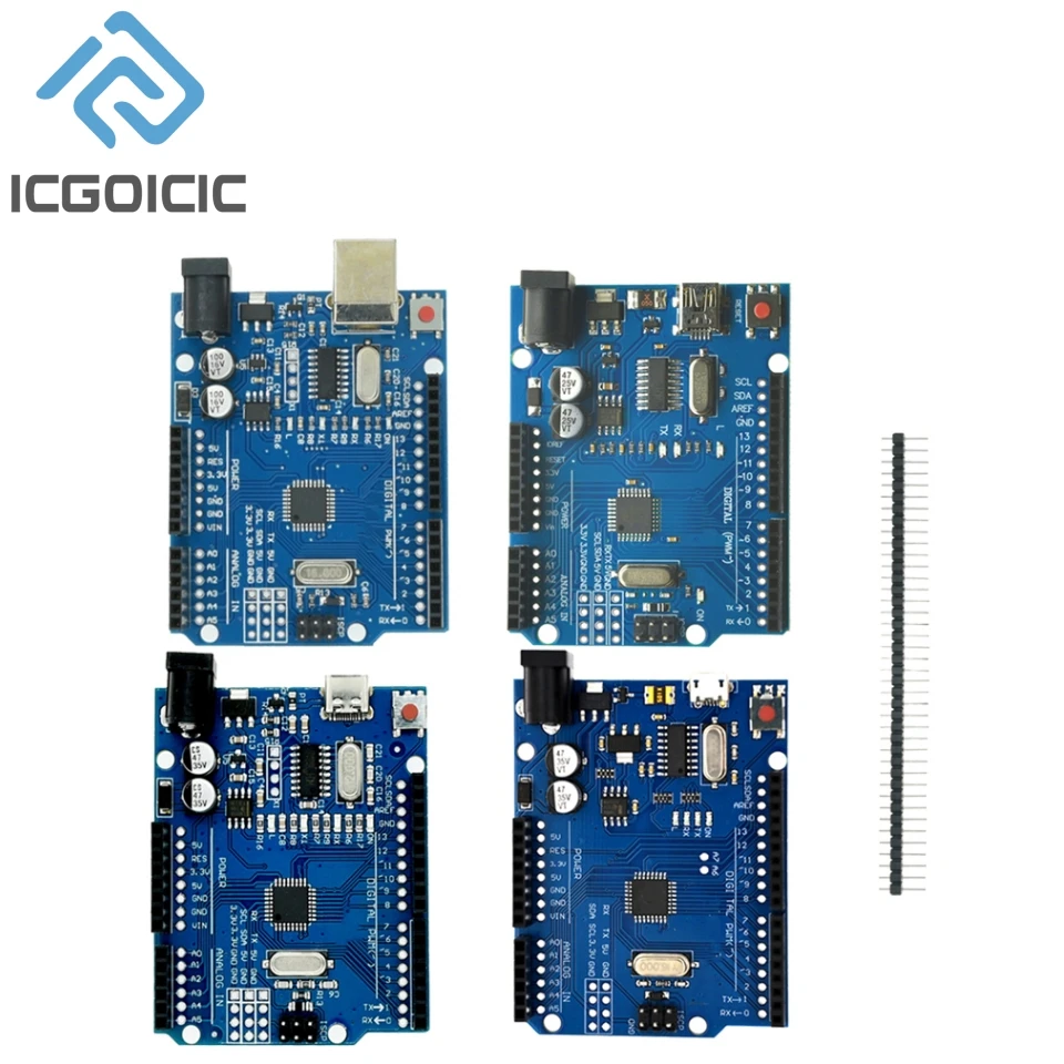
برای این پروژه از ماجیول ریلی، یک برد آردوینو و یک دکمه فشاری استفاده خواهیم کرد. ماجیول ریلی بهعنوان یک سوئیچ عمل میکند که میتواند بارهای AC با ولتاژ بالا مانند یک لامپ را کنترل کند، در حالی که توسط سیگنالهای ولتاژ پایین آردوینو کنترل میشود. ماجیول ریلی سه پایه اصلی برای اتصال بار دارد: مشترک (COM)، در حالت عادی باز (NO) و در حالت عادی بسته (NC).
دکمه فشاری بهعنوان رابط کاربری برای تغییر وضعیت ریلی عمل میکند. این دکمه به یکی از پایههای دیجیتال آردوینو متصل است. وقتی دکمه فشار داده میشود، سیگنالی به آردوینو ارسال میکند که سپس مطابق آن ریلی را فعال یا غیرفعال مینماید. این تعامل ساده به ما اجازه میدهد بهراحتی نور را کنترل کنیم.
جزئیات مشخصات فنی ریلی
| تولیدکننده | سونگل |
|---|---|
| شماره قطعه | SRD-05VDC-SL-C |
| ولتاژ سیمپیچ | 5 ولت جریان مستقیم |
| ولتاژ سوئیچینگ | جریان متناوب 250 ولت / جریان مستقیم 30 ولت |
| جریان سوئیچینگ | حداکثر 10 A |
| مقاومت تماس | کمتر یا مساوی 100 mΩ |
| مقاومت عایق | بزرگتر یا مساوی 1000 MΩ |
| دمای عملیاتی | -40 تا +70 °C |
| بسته | ماجیول ریلی استاندارد |
- اطمینان حاصل کنید که ریلی برای باری که آن را قطع و وصل میکنید، دارای ردهبندی مناسب باشد.
- ماجیول ریلی را با 5 VDC تغذیه نگه دارید.
- برای اتصالات جریان متناوب از عایق مناسب استفاده کنید.
- هنگام کار با برق متناوب (AC) مراقب باشید؛ قبل از اعمال هر تغییر، مطمئن شوید که مدار از برق جدا شده است.
- دکمه فشاری را به پایه ورودی مشخص شده روی آردوینو وصل کنید.
- از حالت INPUT_PULLUP برای پایه دکمه فشاری استفاده کنید تا از نیاز به مقاومتهای خارجی جلوگیری شود.
- قبل از اتصال بارهای جریان متناوب، عملکرد ریلی را با ولتاژ پایینتر آزمایش کنید.
- برای جلوگیری از اتصال کوتاه، اتصالات را بررسی کنید.
دستورالعملهای سیمکشی

برای سیمکشی ماجیول ریلی، ابتدا پایه VCC ریلی را به پایه 5V روی آردوینو و پایه GND ریلی را به پایه GND روی آردوینو متصل کنید. پایه IN ریلی باید به پایه دیجیتال 10 روی آردوینو وصل شود. این پایه سیگنال را برای فعالسازی ریلی ارسال خواهد کرد.
برای دکمه فشاری، یک پایه را به پایه دیجیتال 2 روی آردوینو وصل کنید. پایه دیگر باید به GND وصل شود. این پیکربندی از مقاومت pull-up داخلی آردوینو استفاده میکند، بنابراین مطمئن شوید که در شِفر (کود) پایه روی INPUT_PULLUP تنظیم شده است. زمانی که دکمه فشرده شود، پایه را به حالت LOW میبرد و سیگنالی به آردوینو میفرستد.
برای بار AC، یکی از سیمها را به پایه COM روی ریلی و سیم دیگر را به پایه NO وصل کنید. این پیکربندی اجازه میدهد بار AC هنگام فعال شدن ریلی روشن شود. همیشه مطمئن شوید که اتصالات AC محکم و عایقبندی شدهاند.
نمونههای شِفر (کود) و راهنمای گامبهگام
شِفر (کود) زیر پایههای لازم را مقداردهی اولیه میکند و ریلی را طوری تنظیم میکند که در ابتدا خاموش بماند. فشار دادن دکمه وضعیت ریلی را تغییر میدهد و وضعیت چراغ را متناسب با آن بهروزرسانی میکند.
int pbuttonPin = 2; // connect output to push button
int relayPin = 10; // Connected to relay (LED)

void setup() {
  Serial.begin(9600);
  pinMode(pbuttonPin, INPUT_PULLUP);
  pinMode(relayPin, OUTPUT);
  digitalWrite(relayPin, HIGH); // keep the load OFF at the beginning
}
در شِفر (کود)، متغیرpbuttonPinروی پایه 2 تنظیم شده است که برای دکمه فشاری استفاده میشود. اینrelayPinبه پایه 10 تنظیم شده و ریلی را کنترل میکند. اینdigitalWriteاین تابع برای اطمینان از اینکه ریلی در حالت خاموش (OFF) شروع بهکار میکند استفاده میشود.
void loop() {
  val = digitalRead(pbuttonPin); // read the push button value
  if(val == HIGH && lightON == LOW) {
    pushed = 1 - pushed; // toggle the push status
    delay(100);
  }
  if(pushed == HIGH) {
    digitalWrite(relayPin, LOW); // turn the relay ON
  } else {
    digitalWrite(relayPin, HIGH); // turn the relay OFF
  }
}
این بخش از شِفر (کود) بهطور مداوم وضعیت دکمه فشاری را بررسی میکند. وقتی دکمه فشار داده میشود، حالت آن را تغییر میدهدpushedمتغیر. بسته به مقدارِpushedریلی روشن یا خاموش میشود و در واقع نور را کنترل میکند. این حلقه بهطور مداوم اجرا میشود تا اطمینان حاصل شود که وضعیت نور بهصورت بلادرنگ بهروزرسانی میشود.
برای مشاهدهٔ جزئیات کامل شِفر (کود)، لطفاً به کدی که در پایین مقاله بارگذاری شده است مراجعه کنید.
نمایش / چه انتظاری داشته باشید
وقتی دکمه فشاری را فشار میدهید، ریلی فعال میشود و لامپ AC متصل روشن میشود. با فشار دوبارهٔ دکمه، لامپ خاموش خواهد شد. نمایشگر مسلسل پیامهای وضعیت را نمایش میدهد و نشان میدهد که آیا چراغ روشن است یا خاموش. اگر با مشکلی مواجه شدید، مطمئن شوید که سیمکشی درست است و ورودیهای شناور را بررسی کنید که مبادا باعث رفتار غیرمنتظره شوند (در ویدئو در 10:00).
برچسبهای زمانی ویدیو
- 00:00- مقدمه
- 01:30- مروری بر سختافزار
- 03:15- دستورالعملهای سیمکشی
- ۰۵:45- مرور شِفر (کود)
- 08:00- نمایش
تصاویر

این آموزش بخشی از: کنترل رله با استفاده از آردوینو
- Arduino Code and Video for a Dual-Channel 5V Relay
- کنترل ریلی 5V با استفاده از آردوینو برای راهاندازی بار AC یا DC مانند لامپ یا موتور
- TTP224 حساس(حس کننده) لمسی 4 کاناله برای قطع و وصل بارهای AC/DC با ریلی
- استفاده از ماجیول ریلی ۵ ولت (کم-تحریک) با آردوینو
- استفاده از ماجیول MAX6675 برای ترموکوپل نوع K همراه با ریلی و نمایشگر
- استفاده از سوئیچ رید برای کنترل ریلی و بارهای AC/DC با آردوینو
- استفاده از ماجیول لمسی TTP223B و ریلی برای کنترل بارهای AC/DC با آردوینو
This code has not been parsed yet. Please return to the admin panel to parse it.منابع و مراجع
فایلها📁
هیچ فایلی موجود نیست.