Este tutorial faz parte de: Controlando 16 ou 32 servomotores com PCA9685
Esta coleção de tutoriais em vídeo ajuda você a controlar 32 ou mais servomotores usando Arduino UNO, Nano, Mini ou ESP32. Todos os códigos são fornecidos.

Controlando um Servo Motor de 32 com um Módulo PCA9685 e Sketch Arduino V3 #1: Todos os Servos Juntos
Neste tutorial, vamos aprender como controlar 32 motores servo usando dois módulos de driver PWM PCA9685 conectados a um Arduino. O PCA9685 é um módulo versátil que permite o controle fácil de múltiplos servos via comunicação I2C. Ao final deste projeto, você será capaz de mover todos os 32 servos em uníssono com uma configuração simples.

Também implementaremos um botão que pode ligar ou desligar todos os servos simultaneamente. Este recurso adiciona uma camada extra de controle e torna o projeto mais interativo. Para uma compreensão visual da configuração e do código, não deixe de conferir o vídeo acompanhante (no vídeo em 00:00).
Hardware Explicado
O componente chave neste projeto é o módulo PCA9685, que fornece 16 canais para sinais PWM. Este módulo utiliza comunicação I2C, com os pinos SDA e SCL lidando com a transmissão de dados. Cada PCA9685 pode controlar até 16 servos, mas ao encadear dois módulos, podemos controlar 32 servos simultaneamente.
O Arduino serve como controlador, enviando comandos para os módulos PCA9685. Cada motor servo será conectado a um dos pinos de saída no PCA9685, permitindo controle preciso sobre suas posições. Uma fonte de alimentação externa adequada é crucial, pois os servos podem consumir uma corrente significativa.
Detalhes da Ficha Técnica
| Fabricante | Adafruit |
|---|---|
| Número da peça | PCA9685 |
| Tensão lógica/IO | 3,3 V a 5,5 V |
| Tensão de alimentação | 5 V (externo para servos) |
| Corrente de saída (por canal) | ~20 mA |
| Corrente de pico (por canal) | ~25 mA |
| Orientação sobre frequência PWM | 40 Hz a 1000 Hz |
| Limiares de lógica de entrada | 0,3 V (baixo), 0,7 V (alto) |
| Queda de tensão / RDS(on)saturação | ~0,5 V |
| Limites térmicos | Temperatura de operação: -40°C a +85°C |
| Pacote | TSSOP de 16 pinos |
| Notas / variantes | Pode encadear várias placas para controle expandido. |
- Garanta um fornecimento de energia adequado para evitar a parada do servo.
- Use energia externa para os servos; o Arduino não consegue fornecer corrente suficiente.
- Conecte o terra do PCA9685 ao terra do Arduino.
- Mantenha o pino OE aterrado para habilitar o módulo.
- Observe o endereço I2C de cada módulo; o padrão é 0x40 para o primeiro e 0x41 para o segundo.
Instruções de fiação

Para conectar os módulos PCA9685 e os servos, comece ligando a alimentação e o terra. Conecte o pino VCC do PCA9685 ao pino de 5V do Arduino e conecte o pino de terra ao GND do Arduino. Para a alimentação do servo, use uma fonte de alimentação externa conectada ao pino V+ do PCA9685.
Em seguida, conecte os pinos SDA e SCL dos módulos PCA9685 aos pinos A4 e A5 do Arduino, respectivamente. Se você estiver usando vários módulos PCA9685, conecte-os em cadeia. Certifique-se de que o pino OE esteja conectado ao terra para habilitar as saídas. Por fim, conecte o fio de sinal de cada servo aos respectivos pinos de saída PWM no PCA9685 (0-15 para o primeiro módulo e 16-31 para o segundo módulo).
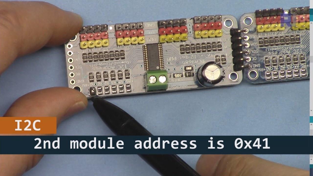
Como mostrado na imagem acima, você deve soldar os pinos mostrados na placa 2, que devem ser diferentes da placa 1. Dessa forma, teremos endereços i2C diferentes e você poderá controlar a placa.
Exemplos de Código e Passo a Passo
Vamos dar uma olhada na parte de configuração do código que inicializa os módulos PCA9685. É aqui que definimos os endereços para cada placa:
Adafruit_PWMServoDriver board1 = Adafruit_PWMServoDriver(0x40);
Adafruit_PWMServoDriver board2 = Adafruit_PWMServoDriver(0x41);
Neste trecho, criamos instâncias do driver PCA9685 para ambas as placas, especificando seus endereços I2C. Esta configuração é crucial para garantir que nosso Arduino possa se comunicar com ambos os módulos.
Osetup()a função inicializa os painéis e define a frequência do PWM:
void setup() {
  Serial.begin(9600);
  board1.begin();
  board2.begin();
  board1.setPWMFreq(60);  // Analog servos run at ~60 Hz updates
  board2.setPWMFreq(60);
}
Aqui, iniciamos a comunicação serial e configuramos ambas as placas para operar a uma frequência de 60 Hz, que é padrão para a maioria dos servos. Isso garante um funcionamento suave enquanto controlamos os servos.
Em seguida, vamos analisar a lógica de controle noloop()function:
for(int angle = 0; angle < 181; angle += 10) {
  for(int i = 0; i < 16; i++) {
    board1.setPWM(i, 0, angleToPulse(angle));
    board2.setPWM(i, 0, angleToPulse(angle));
  }
}
Este loop incrementa o ângulo de 0 a 180 graus em passos de 10. Para cada ângulo, ele define o sinal PWM para todos os servos em ambas as placas, permitindo que se movam em uníssono de 0 a 180 graus e de volta.angleToPulse()a função converte o ângulo na largura de pulso correspondente para os servos.
Demonstração / O que Esperar
Uma vez que tudo esteja conectado e o código carregado, você deve ver todos os 32 servos se movendo juntos, passando pelos ângulos suavemente. Se você pressionar o botão, ele alternará o estado de todos os servos entre ligado e desligado (no vídeo em 00:00). Tenha cuidado com a polaridade reversa e certifique-se de que seus servos estão classificados para a corrente fornecida para evitar superaquecimento.
Carimbos de Tempo do Vídeo
- 00:00 Início
- 01:18 Introdução
- 04:30 Preparando os módulos
- 07:56 fiação explicada
- 10:25 Requisito de energia
- 11:33 Código Explicado
- 19:54 Código 2 Explicado (8 servos juntos em cada placa)
- 20:40 Demonstração de controle de 8 servos juntos
- 21:55 Demonstração Todos os 32 servos se movem juntos
- 22:28 Código para botão de pressão explicado
- 24:43 Fiação para botão de pressão explicada
- 25:12 Demonstração de uso de interruptor de botão pressão
Imagens


Este tutorial é parte de: Controlando 16 ou 32 servomotores com PCA9685
- Código Arduino e vídeo para o controlador de servos PCA9685 de 16 canais e 12 bits V1
- Controle 16 Servos usando um módulo PCA9685 e o sketch Arduino V2 #1: Um por Um
- Controlando 16 Servomotores Usando um Módulo PCA9685 e Esboço Arduino V2: Controle Individual de Servos
- Controlling 16 Servo Motors Using a PCA9685 Module and Arduino V2 Sketch #3: All Servos Together
- Controlando um Motor Servo de 32 usando um Módulo PCA9685 e um ESP32 V4
- Controle 32 Servos via Wi-Fi usando ESP32 e PCA9685 pelo Desktop ou Telefone Móvel V5
/*
 * Original source: https://github.com/adafruit/Adafruit-PWM-Servo-Driver-Library
 *
 * This is the Arduino code to use two PCA6985 boards and control 32 servo motor
 *
 * This is V3 Video on PCA9685: https://youtu.be/6P21wG7N6t4
 *  get this code and wiring from for this video:  http://robojax.com/RJT249
to learn better: watch the video for details (V1) and demo http://youtu.be/y8X9X10Tn1k


 * Written/updated by Ahmad Shamshiri for Robojax Video channel www.Robojax.com
 * Date: Dec 15, 2019, in Ajax, Ontario, Canada

 * Watch video for this code:
 *
 * Related Videos
V5 video of PCA9685 32 Servo with ESP32 with WiFi https://youtu.be/bvqfv-FrrLM
V4 video of PCA9685 32 Servo with ESP32 (no WiFi): https://youtu.be/JFdXB8Za5Os
V3 video of PCA9685 how to control 32 Servo motors https://youtu.be/6P21wG7N6t4
V2 Video of PCA9685 3 different ways to control Servo motors: https://youtu.be/bal2STaoQ1M
V1 Video introduction to PCA9685 to control 16 Servo  https://youtu.be/y8X9X10Tn1k
 * Disclaimer: this code is "AS IS" and for educational purpose only.


or make donation using PayPal http://robojax.com/L/?id=64

 *  * This code is "AS IS" without warranty or liability. Free to be used as long as you keep this note intact.*
 * This code has been download from Robojax.com
    This program is free software: you can redistribute it and/or modify
    it under the terms of the GNU General Public License as published by
    the Free Software Foundation, either version 3 of the License, or
    (at your option) any later version.

    This program is distributed in the hope that it will be useful,
    but WITHOUT ANY WARRANTY; without even the implied warranty of
    MERCHANTABILITY or FITNESS FOR A PARTICULAR PURPOSE.  See the
    GNU General Public License for more details.

    You should have received a copy of the GNU General Public License
    along with this program.  If not, see <https://www.gnu.org/licenses/>.
 */
#include <Wire.h>
#include <Adafruit_PWMServoDriver.h>

// called this way, it uses the default address 0x40
Adafruit_PWMServoDriver board1 = Adafruit_PWMServoDriver(0x40);
Adafruit_PWMServoDriver board2 = Adafruit_PWMServoDriver(0x41);

// Depending on your servo make, the pulse width min and max may vary, you
// want these to be as small/large as possible without hitting the hard stop
// for max range. You'll have to tweak them as necessary to match the servos you
// have!
// Watch video V1 to understand the two lines below: http://youtu.be/y8X9X10Tn1k
#define SERVOMIN  125 // this is the 'minimum' pulse length count (out of 4096)
#define SERVOMAX  575 // this is the 'maximum' pulse length count (out of 4096)


int servoNumber = 0;

void setup() {
  Serial.begin(9600);
  Serial.println("16 channel Servo test!");

  board1.begin();
  board2.begin();
  board1.setPWMFreq(60);  // Analog servos run at ~60 Hz updates
  board2.setPWMFreq(60);
  //yield();
}

// the code inside loop() has been updated by Robojax
void loop() {


    for( int angle =0; angle<181; angle +=10){
      for(int i=0; i<16; i++)
        {
            board2.setPWM(i, 0, angleToPulse(angle) );
            board1.setPWM(i, 0, angleToPulse(angle) );
        }
    }

// robojax PCA9865 16 channel Servo control
  delay(100);

}

/*
 * angleToPulse(int ang)
 * gets angle in degree and returns the pulse width
 * also prints the value on seial monitor
 * written by Ahmad Nejrabi for Robojax, Robojax.com
 */
int angleToPulse(int ang){
   int pulse = map(ang,0, 180, SERVOMIN,SERVOMAX);// map angle of 0 to 180 to Servo min and Servo max
   Serial.print("Angle: ");Serial.print(ang);
   Serial.print(" pulse: ");Serial.println(pulse);
   return pulse;
}/*
* Original source: https://github.com/adafruit/Adafruit-PWM-Servo-Driver-Library
*
* This is the Arduino code for two PAC6985 board to control 16 servo on each board
* total 32 servos using I2C communication
* get this code and wiring from for this video (V3): http://robojax.com/RJT249
watch the video for details (V2) and demo https://youtu.be/6P21wG7N6t4
* watch the video for details (V1) and demo http://youtu.be/y8X9X10Tn1k
* This code is #3 for V2 Video Watch the video :
* I have got 3 codes as follow:https://youtu.be/bal2STaoQ1M
*
#1-Arduino Code to run one by one all servos from 0 to 180°
#2-Arduino Code to control specific servos with specific angle
#3-Arduino Code to run 2 or all servos at together
* Written/updated by Ahmad Shamshiri for Robojax Video channel www.Robojax.com
* Date: Dec 16, 2017, in Ajax, Ontario, Canada
* Permission granted to share this code given that this
* note is kept with the code.
* Disclaimer: this code is "AS IS" and for educational purpose only.
* this code has been downloaded from http://robojax.com/
or make donation using PayPal http://robojax.com/L/?id=64
* * This code is "AS IS" without warranty or liability. Free to be used as long as you keep this note intact.*
* This code has been download from Robojax.com
This program is free software: you can redistribute it and/or modify
it under the terms of the GNU General Public License as published by
the Free Software Foundation, either version 3 of the License, or
(at your option) any later version.
This program is distributed in the hope that it will be useful,
but WITHOUT ANY WARRANTY; without even the implied warranty of
MERCHANTABILITY or FITNESS FOR A PARTICULAR PURPOSE. See the
GNU General Public License for more details.
You should have received a copy of the GNU General Public License
along with this program. If not, see <https://www.gnu.org/licenses/>.
*/
#include <Wire.h>
#include <Adafruit_PWMServoDriver.h>
// called this way, it uses the default address 0x40
Adafruit_PWMServoDriver board1 = Adafruit_PWMServoDriver(0x40);
Adafruit_PWMServoDriver board2 = Adafruit_PWMServoDriver(0x41);
// Depending on your servo make, the pulse width min and max may vary, you
// want these to be as small/large as possible without hitting the hard stop
// for max range. You'll have to tweak them as necessary to match the servos you
// have!
// Watch video V1 to understand the two lines below: http://youtu.be/y8X9X10Tn1k
#define SERVOMIN 125 // this is the 'minimum' pulse length count (out of 4096)
#define SERVOMAX 575 // this is the 'maximum' pulse length count (out of 4096)
int servoNumber = 0;
void setup() {
Serial.begin(9600);
Serial.println("16 channel Servo test!");
board1.begin();
board2.begin();
board1.setPWMFreq(60); // Analog servos run at ~60 Hz updates
board2.setPWMFreq(60);
//yield();
}
// the code inside loop() has been updated by Robojax
void loop() {
for( int angle =0; angle<181; angle +=10){
for(int i=0; i<8; i++)
{
board2.setPWM(i, 0, angleToPulse(angle) );
board1.setPWM(i, 0, angleToPulse(angle) );
}
}
for( int angle =0; angle<181; angle +=30){
for(int i=8; i<16; i++)
{
board2.setPWM(i, 0, angleToPulse(angle) );
board1.setPWM(i, 0, angleToPulse(angle) );
}
}
// robojax PCA9865 16 channel Servo control
delay(100);
}
/*
* angleToPulse(int ang)
* gets angle in degree and returns the pulse width
* also prints the value on serial monitor
* written by Ahmad Shamshiri for Robojax, Robojax.com
*/
int angleToPulse(int ang){
int pulse = map(ang,0, 180, SERVOMIN,SERVOMAX);// map angle of 0 to 180 to Servo min and Servo max
Serial.print("Angle: ");Serial.print(ang);
Serial.print(" pulse: ");Serial.println(pulse);
return pulse;
}
 /* Original source: https://github.com/adafruit/Adafruit-PWM-Servo-Driver-Library
 *
 * This is the Arduino code for two PAC6985 board  and push button

 * total 32 servos using I2C communication
 * get this code and wiring from for this video (V3):  http://robojax.com/RJT249


 * watch the video for details (V1) and demo http://youtu.be/y8X9X10Tn1k
 *  This code is #3 for V2 Video Watch the video :
 *  I have got 3 codes as follow:https://youtu.be/bal2STaoQ1M
 *
   #1-Arduino Code to run one by one all servos from 0 to 180°
   #2-Arduino Code to control specific servos with specific angle
   #3-Arduino Code to run 2 or all servos at together

 * Written/updated by Ahmad Shamshiri for Robojax Video channel www.Robojax.com
 * Date: Dec 16, 2017, in Ajax, Ontario, Canada
 * Permission granted to share this code given that this
 * note is kept with the code.
 * Disclaimer: this code is "AS IS" and for educational purpose only.


 *  * This code is "AS IS" without warranty or liability. Free to be used as long as you keep this note intact.*
 * This code has been download from Robojax.com
    This program is free software: you can redistribute it and/or modify
    it under the terms of the GNU General Public License as published by
    the Free Software Foundation, either version 3 of the License, or
    (at your option) any later version.

    This program is distributed in the hope that it will be useful,
    but WITHOUT ANY WARRANTY; without even the implied warranty of
    MERCHANTABILITY or FITNESS FOR A PARTICULAR PURPOSE.  See the
    GNU General Public License for more details.

    You should have received a copy of the GNU General Public License
    along with this program.  If not, see <https://www.gnu.org/licenses/>.
 */
#include <Wire.h>
#include <Adafruit_PWMServoDriver.h>

// called this way, it uses the default address 0x40
Adafruit_PWMServoDriver board1 = Adafruit_PWMServoDriver(0x40);
Adafruit_PWMServoDriver board2 = Adafruit_PWMServoDriver(0x41);

// Depending on your servo make, the pulse width min and max may vary, you
// want these to be as small/large as possible without hitting the hard stop
// for max range. You'll have to tweak them as necessary to match the servos you
// have!
// Watch video V1 to understand the two lines below: http://youtu.be/y8X9X10Tn1k
#define SERVOMIN  125 // this is the 'minimum' pulse length count (out of 4096)
#define SERVOMAX  575 // this is the 'maximum' pulse length count (out of 4096)

#define PUSH_BUTTON_PIN 2
#define OE_PIN 8

int boardState= LOW;
int showDebug=0;
int angle = 0;
int angleStep =10;

void setup() {
  Serial.begin(9600);
  Serial.println("16 channel Servo test!");

  board1.begin();
  board2.begin();
  board1.setPWMFreq(60);  // Analog servos run at ~60 Hz updates
  board2.setPWMFreq(60);

  pinMode(PUSH_BUTTON_PIN,INPUT_PULLUP);
  pinMode(OE_PIN, OUTPUT);
  digitalWrite(OE_PIN,LOW);//turn module ON

}

// the code inside loop() has been updated by Robojax
void loop() {
   if(digitalRead(PUSH_BUTTON_PIN) == LOW)
   {
    boardState = 1-boardState;
    Serial.println("push button pressed");
    delay(200); // give the finger time
   }
 digitalWrite(OE_PIN, boardState);
    for( int angle =0; angle<181; angle +=angleStep){
      delay(50);
      for(int i=0; i<16; i++)
        {
          board1.setPWM(i, 0, angleToPulse(angle) );
          board2.setPWM(i, 0, angleToPulse(angle) );
        }
    }

// robojax PCA9865 16 channel Servo control
  delay(100);

}

/*
 * angleToPulse(int ang)
 * gets angle in degree and returns the pulse width
 * also prints the value on serial monitor
 * written by Ahmad Shamshiri for Robojax, Robojax.com
 */
int angleToPulse(int ang){
   int pulse = map(ang,0, 180, SERVOMIN,SERVOMAX);// map angle of 0 to 180 to Servo min and Servo max
  if(showDebug)
  {
   Serial.print("Angle: ");Serial.print(ang);
   Serial.print(" pulse: ");Serial.println(pulse);
  }
   return pulse;
}

/*
 * updateState()
 * @brief reads push buttons and updates values
 * @param none
 * @return no return
 * Written by Ahmad Shamshiri for robojax.com
 * on Nov 01, 2019 at 18:10 in Ajax, Ontario, Canada
 */
void updateState()
{
   if(digitalRead(PUSH_BUTTON_PIN) == LOW)
   {
    boardState = 1-boardState;
    Serial.println("push button pressed");
    delay(200); // give the finger time
   }
   digitalWrite(OE_PIN, boardState);
}//updateState end
Coisas que você pode precisar
-
AmazonasCompre o PCA9685 na Amazonamzn.to
-
eBayCompre o PCA9685 no eBayebay.us
-
AliExpressCompre PCA9685 na AliExpresss.click.aliexpress.com
-
BanggoodCompre PCA9685 na Banggoodbanggood.com
Recursos e referências
Ainda não há recursos.
Arquivos📁
Bibliotecas do Arduino (zip)
-
Adafruit-PWM-Servo-Driver-Library-master
Adafruit-PWM-Servo-Driver-Library-master.zip0.02 MB