本教程是的一部分: 使用 Arduino 控制继电器
这里是所有与接力赛相关的视频合集。其他视频的链接在本文下方。

Using a MAX6675 K-Type Thermocouple with Relay and Display
This project demonstrates how to interface a MAX6675 K-type thermocouple with an Arduino, incorporating a relay for control and a display for temperature readings. This setup is invaluable for various applications where precise temperature monitoring and automated responses are needed. Here are some project ideas:

- Overheat protection for sensitive electronics
- Temperature-controlled incubator for biological experiments
- Automated brewing system for coffee or beer
- Industrial process monitoring and control
- Environmental monitoring in a greenhouse or other controlled environment
Hardware/Components
To build this project, you will need the following components:
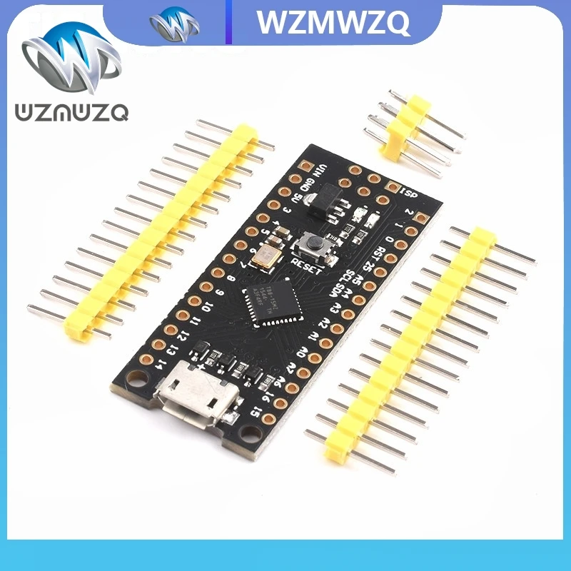
- Arduino Uno (or compatible board)
- MAX6675 K-type thermocouple module (in video at 00:58)
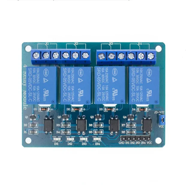
- Relay module
- TM1637 4-digit LED display module
- Jumper wires
- Connecting wires
Wiring Guide
The wiring is explained in the video (in video at 05:36). The specific connections depend on whether you are using a surface mount chip or a PCB module. Refer to the video for a detailed wiring diagram.

Code Explanation
The Arduino code uses the MAX6675 library to read temperature values from the thermocouple. The key configurable parts of the code are:
- Thermocouple pin definitions:
thermoDO,thermoCS, andthermoCLK(in video at [03:53]). These pins need to be adjusted according to your wiring scheme. - Relay control pin: Pin 10 is used to control the relay (in video at [05:36]). Change this if needed.
- Display configuration (if used): The code includes sections for configuring the TM1637 display. Adjust the CLK and DIO pins if necessary (in video at [03:53]).
The code includes functions to read temperature in Celsius and Fahrenheit. A crucial part of the code is the conditional statement that checks if the temperature exceeds a threshold (80.0°C in this example). If it does, the relay is activated (pin 10 goes LOW).
// If temperature goes above 80.0C, turn the relay ON
if(thermocouple.readCelsius() > 80.00){
  digitalWrite(10, LOW);// Set pin 10 LOW
} else {
  digitalWrite(10, HIGH);// Set pin 10 HIGH
}
Live Project/Demonstration
The video demonstrates the project in action (in video at 06:59). The sensor accurately reads the ambient temperature and increases when heated. The relay functionality is also showcased.
Chapters
- [00:00] Introduction
- [00:39] Sensor Overview
- [01:40] Pin Connections
- [02:22] Library Installation
- [03:53] Code Explanation (Setup)
- [04:06] Code Explanation (Loop)
- [05:36] Wiring
- [06:59] Live Demonstration
图像


本教程是……的一部分: 使用 Arduino 控制继电器
- Arduino Code and Video for a Dual-Channel 5V Relay
- Controlling a 5V Relay Using Arduino to cotrol AC or DC load like bulb or motor
- TTP224 4-Channel Touch Sensor to Turn AC/DC Loads with Relay
- 使用5V继电器模块(低触发)与Arduino
- Using a Reed Switch to Control a Relay and AC/DC Loads with an Arduino
- Using a TTP223B touch module and relay to control AC/DC loads with an Arduino
- Using an Arduino push button to switch a relay and AC bulb
This code has not been parsed yet. Please return to the admin panel to parse it.This code has not been parsed yet. Please return to the admin panel to parse it.This code has not been parsed yet. Please return to the admin panel to parse it.This code has not been parsed yet. Please return to the admin panel to parse it.资源与参考
文件📁
没有可用的文件。