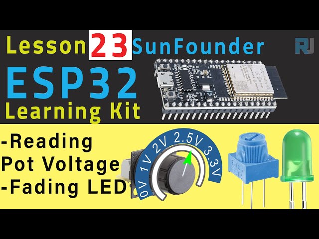
In this tutorial, we will learn how to measure the DC voltage from a potentiometer using the ESP32 module from SunFounder. The project will also demonstrate how to fade an LED based on the potentiometer's position. As you turn the potentiometer counterclockwise, the voltage reading decreases and the LED fades accordingly. This exercise will provide a practical understanding of using the analog-to-digital converter (ADC) in the ESP32.
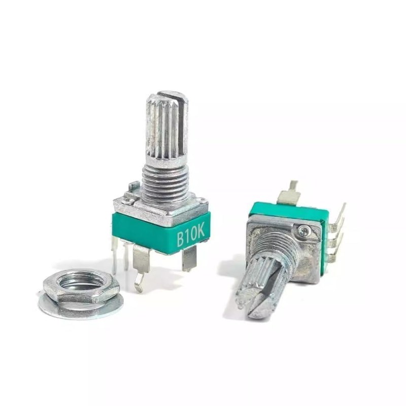
potentiometerPotentiometer or variable resistor
The ESP32 is a powerful microcontroller equipped with built-in Wi-Fi and Bluetooth capabilities, making it ideal for IoT projects. In this tutorial, we will utilize its analog input features to read voltage levels from a potentiometer, while also controlling an LED's brightness based on these readings. The outcome will be a responsive LED that varies its intensity as you adjust the potentiometer.
Hardware Explained
For this project, we will require the following components:
ESP32 Module: The main microcontroller that will read the potentiometer's voltage and control the LED.
Potentiometer: A variable resistor used to adjust the voltage. It has three pins: two for fixed resistors and one that varies.
LED: A light-emitting diode whose brightness will be controlled based on the potentiometer's position.
Resistor: A 220-ohm resistor to limit the current through the LED.
The potentiometer works by varying the resistance between its pins, allowing it to generate a voltage that the ESP32 can read through its ADC. The LED brightness is controlled using Pulse Width Modulation (PWM) to adjust the power delivered to it based on the analog reading.
Datasheet Details
Wiring Instructions
ESP32-23-fading-LED_pot-wiring
To wire the components, start by connecting the potentiometer. Connect one of its outer pins to the 3.3V power supply on the ESP32. Connect the other outer pin to the ground (GND). The middle pin of the potentiometer will connect to pin 35 on the ESP32, which is used for reading the analog voltage.
Next, for the LED, connect the longer pin (anode) to pin 26 on the ESP32 through a 220-ohm resistor. Connect the shorter pin (cathode) of the LED to the ground. Ensure that all connections are secure and double-check the orientation of the LED to prevent damage.
Code Examples & Walkthrough
The following code snippet demonstrates how to set up the ESP32 to read the potentiometer and control the LED:
const int potPin = 35; // Potentiometer connected to
const int ledPin = 26; // LED connected to

// PWM settings
const int freq = 5000; // PWM frequency
const int resolution = 12; // PWM resolution (bits)
In this excerpt, we define the pins for the potentiometer and the LED. The PWM frequency and resolution are also set, which will determine the LED's brightness levels.
In the setup function, we initialize the serial communication and configure the PWM settings for the LED. This setup runs once when the program starts.
Finally, the loop function continuously reads the potentiometer value and adjusts the LED brightness:
void loop() {
  int potValue = analogRead(potPin); // read the value of the potentiometer
  uint32_t voltage_mV = analogReadMilliVolts(potPin); // Read the voltage in millivolts

  ledcWrite(ledPin, potValue);
  // Serial output omitted for brevity
}
In the loop, we read the analog value from the potentiometer and translate it to control the LED brightness. The serial output shows the potentiometer value and voltage, helping to verify the readings.
Demonstration / What to Expect
When the circuit is properly set up and the code is uploaded, turning the potentiometer should result in a corresponding change in the voltage reading displayed in the serial monitor. The LED should fade smoothly in and out as the potentiometer is adjusted. If the LED does not respond as expected, check the wiring connections and ensure the potentiometer is functioning correctly (in video at 11:30).
Video Timestamps
00:00 Start
2:02 What is Pot
4:15 Measuring the resistance of pot
6:59 Documentation page
8:56 Wiring explained
12:28 Arduino code explained
15:58 Selecting ESP32 board and COM port in Arduino IDE
17:40 Demonstration of reading pot value with ESP32