How to use MPU-6050 Accelerometer and Gyroscope Module
The MPU-6050 is a versatile sensor that combines a 3-axis accelerometer and a 3-axis gyroscope in a single package. In this tutorial, we will explore how to interface this module with an Arduino to measure acceleration and angular velocity. The outcome will be a simple program that displays real-time data from the sensor, allowing you to monitor both the acceleration and orientation of your device.

By following this guide, you will learn how to set up the hardware, wire the components correctly, and write the necessary code to get the MPU-6050 up and running. This will provide you with a foundation for further projects involving motion sensing and orientation detection. For additional clarity, be sure to check the video accompanying this tutorial (in video at 00:00).
Hardware Explained
The main component in this project is the MPU-6050 sensor, which provides both accelerometer and gyroscope data. The accelerometer measures linear acceleration along the X, Y, and Z axes, while the gyroscope measures rotational rates around those same axes. This combination makes the MPU-6050 an excellent choice for applications that require motion tracking.
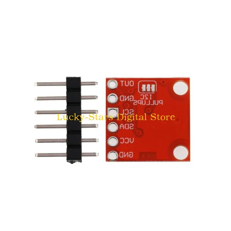
Additionally, the module uses an I2C interface for communication, which simplifies connections and allows multiple devices to be connected on the same bus. The sensor is powered through the VCC pin, which typically requires a voltage between 3.3V and 5V. Ground is connected to the common ground of the Arduino.
Datasheet Details
| Manufacturer | InvenSense |
|---|---|
| Part number | MPU-6050 |
| Logic/IO voltage | 3.3 – 5 V |
| Supply voltage | 3.3 – 5 V |
| Output current (per channel) | … |
| Peak current (per channel) | … |
| PWM frequency guidance | … |
| Input logic thresholds | … |
| Voltage drop / RDS(on) / saturation | … |
| Thermal limits | … |
| Package | QFN |
| Notes / variants | … |
- Connect the VCC pin to 3.3V or 5V.
- Connect the GND pin to ground.
- Use I2C communication via SDA (data) and SCL (clock).
- Ensure pull-up resistors are present on SDA and SCL lines.
- Check for proper voltage levels to avoid damaging the sensor.
Wiring Instructions

To wire the MPU-6050 to your Arduino, start by connecting the VCC pin of the MPU-6050 to the 5V pin on the Arduino. Next, connect the GND pin of the MPU-6050 to one of the GND pins on the Arduino. For I2C communication, connect the SDA pin of the MPU-6050 to the Arduino's A4 pin, and the SCL pin to the A5 pin. Ensure that your Arduino is set to use I2C communication by including the appropriate libraries in your code.
Double-check your connections before powering the system. If using a breadboard, ensure that the connections are secure and that there are no short circuits. If the module does not respond as expected, verify the wiring and check the I2C address of the MPU-6050 in your code.
Code Examples & Walkthrough
The following code snippet initializes the MPU-6050 and begins to read data from it. The key identifiers include mpu6050, which is the instance of the MPU6050 class, and timer, which is used to control the timing of data output.
MPU6050 mpu6050(Wire);
long timer = 0;

void setup() {
  Serial.begin(9600);
  Wire.begin();
  mpu6050.begin();
  mpu6050.calcGyroOffsets(true);
}
In this setup function, we initialize the serial communication and the MPU-6050 sensor. The mpu6050.calcGyroOffsets(true) call is crucial as it calibrates the gyroscope offsets, ensuring accurate readings.
In the loop function, we continuously update the sensor data and print it to the serial monitor. The following code snippet shows how to read and print the temperature and acceleration data:
if(millis() - timer > 1000){
  Serial.print("temp : ");Serial.println(mpu6050.getTemp());
  Serial.print("accX : ");Serial.print(mpu6050.getAccX());
  Serial.print("\taccY : ");Serial.print(mpu6050.getAccY());
  Serial.print("\taccZ : ");Serial.println(mpu6050.getAccZ());
}
This block checks if a second has passed since the last output. It then retrieves the temperature and acceleration values from the MPU-6050 and prints them to the serial monitor. You can observe these values updating in real-time.
Demonstration / What to Expect
Once everything is wired and the code is uploaded, you can expect to see the temperature and acceleration data printed in the serial monitor every second. If you tilt or move the MPU-6050, the acceleration values should change accordingly. Be mindful that incorrect wiring or insufficient power supply can lead to erratic readings or no data at all (in video at 01:30).
Изображения


This code has not been parsed yet. Please return to the admin panel to parse it.This code has not been parsed yet. Please return to the admin panel to parse it.Вещи, которые могут вам понадобиться
-
АмазонкаКупите MPU-6050 на Amazonamzn.to
Ресурсы и ссылки
-
ВнешнийВеб-сайт производителяinvensense.com
Файлы📁
Библиотеки Arduino (zip)
-
Библиотека Arduino для MPU9250
robojax-MPU9250-master.zip3.38 MB