Turn an ESP32 Touchscreen Into a Piano – No Sound Files Needed
Raised keys, real chords, and the sound generated on the chip
A playable piano on the touchscreen. The keys look raised and press in when you touch them, the touch panel tracks five fingers so you can play chords, and every note is synthesised by the processor - there are no sound files and no SD card involved.
922-This is AI Music Article project is here.
923-The Piano (is this current article)
It is completely offline. Flash it and play.
Robojax_Makerfab at checkout on the MaTouch AI ESP32-S3 product page. It costs you nothing to use, and it helps support the free code and tutorials here.Two layouts, and why both exist
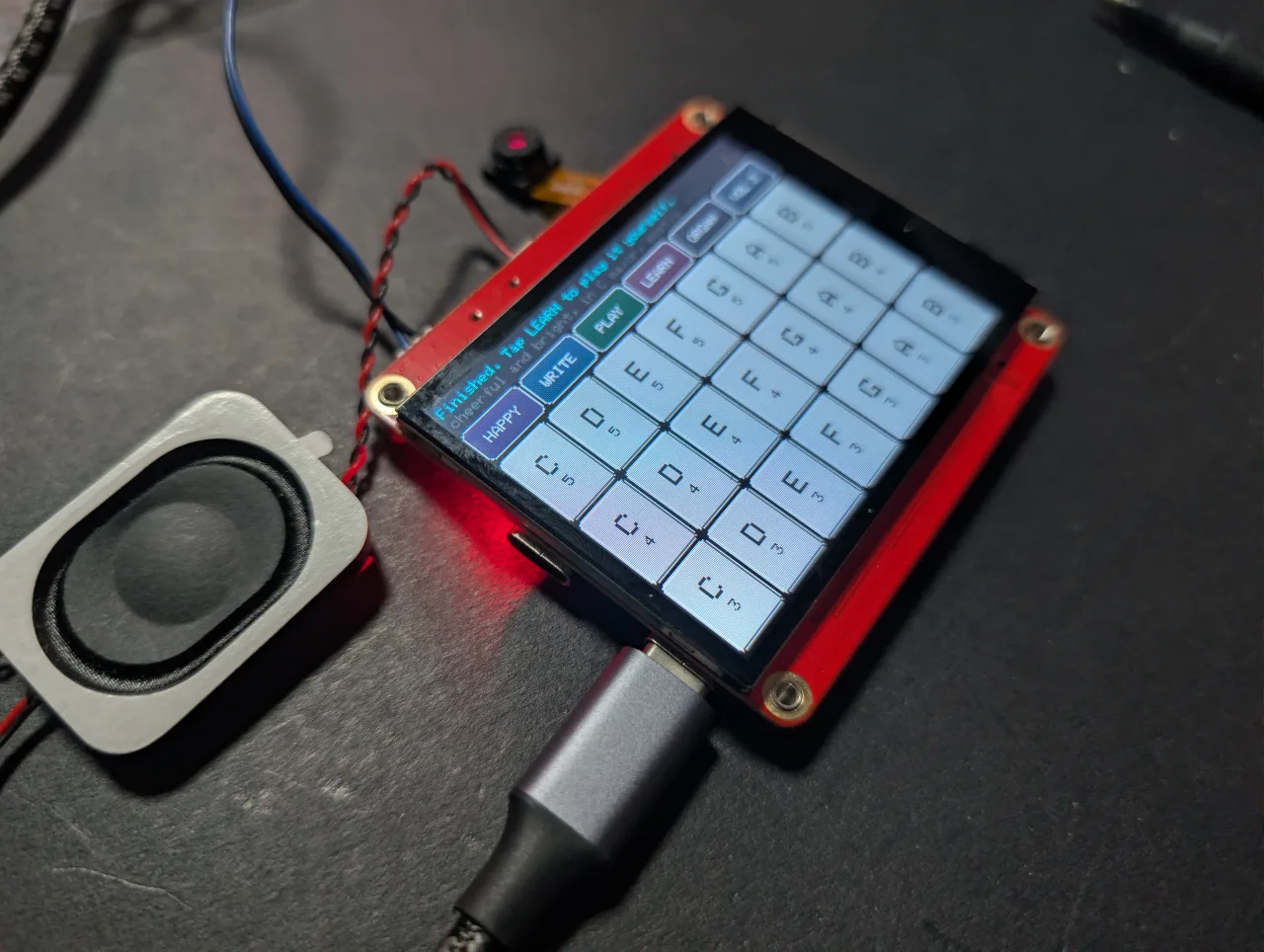
This sketch has two completely different keyboards, and a LAYOUT button in the top-left corner swaps between them. The label on that button tells you which one you are in right now, so it doubles as the indicator - tap it and it changes.
KEYS - a real piano
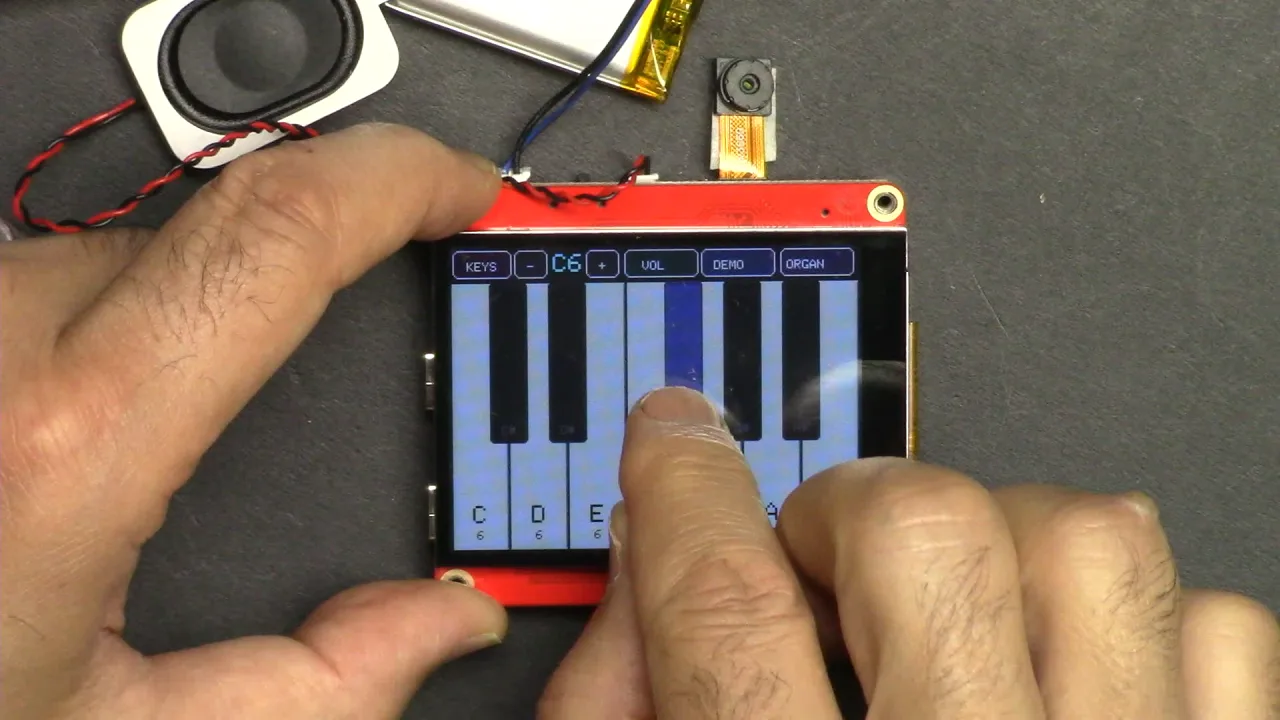
Seven white keys across the full width with five black keys sitting on top, exactly like a real keyboard. This is what the board starts on. Because only one octave fits, the - and + buttons beside LAYOUT move you up and down; the cyan readout between them shows where you are, C3 through C6.
GRID - four octaves, no wrong notes
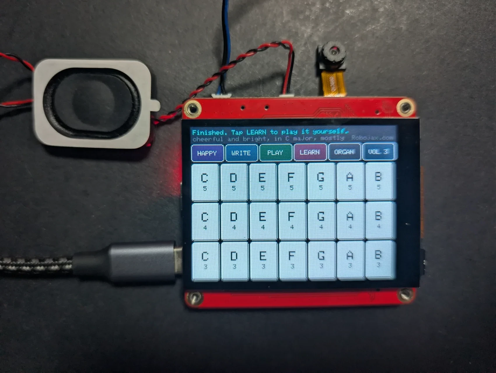

Four rows of seven, 28 keys at once. Each row is an octave, lowest at the bottom; each column is a note - C, D, E, F, G, A, B. No sharps, no flats, so the whole board is C major and there are no wrong notes. You can hand it to somebody who has never played anything, let them hit it at random, and it still sounds like music.
Why one octave is all that fits as a real keyboard
This is the arithmetic that shapes the whole project. The screen is 320 pixels across but only about 2.2 inches wide, so a fingertip covers roughly 45 pixels.
- One octave - seven white keys at about 45 pixels each. Comfortable.
- Two octaves - fourteen white keys at about 22 pixels each. Half a fingertip. Unplayable.
So a proper piano layout can only ever show one octave here, which is why the octave buttons exist - and why the grid exists as the alternative when you want range and reliability instead of realism.
Changing the layout in code
Three settings near the top of the sketch control all of this:
| Setting | What it does |
|---|---|
BOOT_LAYOUT |
Which keyboard appears at power-on. LAYOUT_KEYS for the piano, LAYOUT_GRID for the grid. |
ROWS |
How many octaves the GRID shows. Default 4. |
COLS |
Notes per row in the GRID. Default 7, the seven naturals. |
BASE_OCTAVE |
Which octave the bottom row of the GRID starts on. Default 3. |
ROWS and COLS only affect the GRID. The KEYS layout builds its octave from its own tables and ignores them, so changing those numbers will not add black keys or change the piano.How the raised look is done
A light edge along the top and left of each key, and a dark edge along the bottom and right, reads to the eye as something sticking out. Pressing a key swaps them and darkens the face, which reads as pushed in. It is two lines of code per edge and it is convincing.
How the sound is made
There are no recordings anywhere on this board. No samples, nothing on the memory card. Each note is a phase accumulator stepping through a 512-entry sine table - step through it quickly for a high note, slowly for a low one - so no trigonometry is calculated per sample. Three harmonics are mixed for warmth.
Every note also gets a short attack and release envelope, about six milliseconds in and seventy out. Without it you hear a click every time a note starts or stops, because you are switching a waveform on at full amplitude. That envelope is the difference between an instrument and a beeper.
Up to five notes are mixed together, matching the five touch points the panel reports. i2s_write() blocks when the audio buffer is full, which conveniently paces the whole program at real time - no timers or interrupts are needed.
The buttons
- LAYOUT swaps between KEYS and GRID. The label shows which one you are in.
- - and + move the octave. KEYS layout only.
- VOL opens a volume panel over the keyboard - drag the bar to set the level. Tap VOL again to close it.
- DEMO plays a tune by itself, lighting each key as it goes.
- WAVE cycles the tone between SOFT, ORGAN and BRIGHT. It starts on ORGAN, which suits this small speaker best, but try all three.
Volume control
The amplifier on this board is genuinely loud - 3.2 W into a 4 Ω speaker - so being able to turn it down matters. Tapping VOL slides a panel over the keyboard with a large draggable bar; the current level is also shown permanently in the top bar.
While the panel is open it deliberately swallows every touch below the top bar, so you cannot set off notes through it by accident. The setting is applied as a single multiplication when the mixed audio is scaled to 16-bit, which costs nothing at run time and affects the demo tune equally. Adjust VOL_STEPS in the sketch if you want finer or coarser steps than the default ten.
No WiFi, no accounts, nothing to set up
Worth saying plainly, because every other project in this series needs an account somewhere: this one does not. There is no secrets.h to fill in, no API key, no network. Flash it and play. Of everything built for this board, this is the one to hand to a beginner.
Try a chord
Press three or four keys at once. The touch controller tracks five fingers, so they all sound together - that is the moment it stops feeling like a beeper and starts feeling like an instrument.
About the MaTouch AI ESP32-S3 2.8" board
Every project on this page runs on the MaTouch AI ESP32-S3 2.8" TFT ST7789V from Makerfabs. It is an all-in-one board: a colour touchscreen, a 3 megapixel camera, two microphones and a real speaker amplifier, all driven by an ESP32-S3 with 8 MB of PSRAM. That combination is what makes these AI projects possible on a single board with nothing else attached.
The 8 MB of PSRAM matters more than any other number here. It is what lets the board hold a camera frame, a few seconds of recorded audio, or a base64-encoded photo in memory at the same time - none of which fits in the ESP32’s normal RAM.
Manufacturer documentation: Makerfabs wiki page.
Every other project for this board - the camera, offline face recognition, the AI voice assistant, AI vision and the drawing project - has its own tutorial. Links to all of them are below this article.
Key specifications
- Processor: ESP32-S3, dual core 240 MHz, WiFi 2.4 GHz + Bluetooth 5.0
- Memory: 16 MB flash, 8 MB PSRAM (required by nearly every project here)
- Display: 2.8" IPS, 320×240, ST7789V driver, SPI
- Touch: GT911 capacitive, tracks 5 fingers at once
- Camera: OV3660, 3 megapixel, up to 2048×1536
- Microphones: two INMP441 I2S digital mics (a genuine stereo pair)
- Speaker: MAX98357A class-D amplifier, 3.2 W into 4 Ω
- Storage: microSD card slot (SPI mode)
- Power: USB-C, JST battery connector, TP4056 charger, power switch
- Also on board: WS2812B RGB LED, PCF8563T battery-backed real-time clock, and a MAX17048 battery fuel gauge that is not listed in the official specifications
USB CDC On Boot to Disabled. Use the wrong port and audio will misbehave or uploads will fail.Powering it from a battery? The two USB-C sockets, the TP4056 charger and the power switch are explained in full, with the schematic, in the board test article — including which socket charges and whether the switch should be on or off.
Arduino IDE settings
These settings matter. Most problems people report with this board are one of these being wrong, and they reset when you change the core version, so check them again after any change.
| Setting | Value |
|---|---|
| Board | ESP32S3 Dev Module |
| ESP32 core version | 2.0.17 |
| PSRAM | OPI PSRAM |
| Flash Size | 16MB (128Mb) |
| Partition Scheme | 16M Flash (3MB APP/9.9MB FATFS) |
| USB CDC On Boot | Disabled |
| Upload Speed | 921600 |
| Erase All Flash Before Upload | Disabled |
| Port | the CH340K USB-C port |
If the upload fails: putting the board into download mode by hand
Most of the time you just press Upload and it works. Sometimes it does not - the IDE sits at Connecting...... and then gives up with Failed to connect to ESP32-S3: No serial data received.
That happens because IO0 does three jobs on this board at once: it is the BOOT button, it is the auto-reset line from the CH340K, and it is the data line for the RGB LED. When the sketch already running on the board is driving that LED, it can fight the automatic reset, so the chip restarts into your old sketch instead of into the bootloader.
The fix takes five seconds. Put it into download mode yourself:
- Press and hold the BOOT button.
- While still holding BOOT, press RESET and let go of RESET.
- Now let go of BOOT. The screen goes blank - that is the bootloader waiting.
- Click Upload.
- When it finishes, press RESET once to run the new sketch.
If it still will not connect, drop Upload Speed to 115200 and try again. And check the board’s power switch is on - the CH340K enumerates and gives you a COM port even when the board itself is switched off, which fools people.
Required libraries
This project needs every library in the table below - nothing more, nothing less. Most install straight from Tools → Manage Libraries in the Arduino IDE, but GFX Library for Arduino has to be installed from a ZIP file. The version numbers matter, so please use exactly the ones listed.
| Library | Version | Author | Install from |
|---|---|---|---|
| GFX Library for Arduino | 1.5.6 | moononournation | ZIP file - see below |
| bb_captouch | 1.3.1 | Larry Bank | Library Manager |
| Adafruit NeoPixel | any recent | Adafruit | Library Manager |
Installing the GFX library from a ZIP file
- Download the ZIP. It is included in this project’s download, or you can get it from the Arduino_GFX repository - click the green Code button, then Download ZIP.
- Save it somewhere you can find it again. Do not unzip it.
- In the Arduino IDE, click Sketch → Include Library → Add .ZIP Library.
- Browse to the ZIP file you downloaded and click Open.
- The IDE installs it and confirms at the bottom of the window. If you already have a 1.6 version installed, delete that folder from
Documents/Arduino/librariesfirst, or the two will conflict.
Troubleshooting
| Symptom | Cause and fix |
|---|---|
| Screen stays black | Wrong GFX library version (use 1.5.6) or wrong board settings. |
PSRAM alloc failed |
Tools → PSRAM is not set to OPI PSRAM. |
| Nothing uploads / no COM port | Wrong USB-C port, or the CH340 driver is not installed. |
Imágenes
Recursos y referencias
Aún no hay recursos.
Archivos📁
No hay archivos disponibles.