Allegro ACS758 전류 센서와 LCD 및 과전류 보호 기능을 갖춘 Arduino용
이 튜토리얼에서는 Allegro ACS758 전류 센서를 LCD와 함께 사용하여 전류 값을 표시하고 과전류 보호를 구현하는 방법을 배우게 됩니다. 이 설정을 통해 전류를 모니터링하고 사전 정의된 한계를 초과하면 부하를 자동으로 차단할 수 있습니다. 이 프로젝트는 하드웨어와 소프트웨어 구성 요소를 결합하여 기능적인 전류 모니터링 시스템을 만듭니다.

이 가이드를 따르면 구성 요소를 올바르게 배선하고 코드 뒤에 있는 프로그래밍 로직을 이해할 수 있습니다. 더 시각적인 설명을 위해 관련 비디오(비디오의 00:00 시점)를 확인하세요.
하드웨어 설명
이 프로젝트의 주요 구성 요소에는 Allegro ACS758 전류 센서, I2C 인터페이스가 있는 LCD1602 디스플레이, Arduino 보드가 포함됩니다. ACS758 센서는 이를 통과하는 전류를 측정하고 전류에 비례하는 전압을 출력합니다. LCD1602는 전류 값과 상태 메시지를 표시하고, Arduino는 데이터를 처리하고 과전류 보호를 위해 릴레이를 제어합니다.
ACS758 센서는 홀 효과 감지라는 원리로 작동하며, 직접적인 전기 접촉 없이 전류를 측정할 수 있습니다. 출력 전압은 통과하는 전류의 양에 따라 변하므로 전기 부하를 안전하고 효율적으로 모니터링할 수 있는 방법을 제공합니다.
데이터시트 세부 정보
| 제조업체 | Allegro MicroSystems |
|---|---|
| 부품 번호 | ACS758 |
| 로직/IO 전압 | 3.3V / 5V |
| 공급 전압 | 5V |
| 출력 전류(채널당) | 최대 200A |
| 피크 전류(채널당) | 200A |
| PWM 주파수 가이드 | 해당 없음 |
| 입력 로직 임계값 | 0.5 x VCC(양방향) |
| 전압 강하 / RDS(on) / 포화 | 해당 없음 |
| 열 한계 | 150°C |
| 패키지 | PCB 장착 |
| 참고 사항 / 변형 | 다양한 전류 범위에 대해 여러 모델 사용 가능 |
- 최대 정격에 가깝게 작동하는 경우 적절한 방열판을 확보하세요.
- 전원 공급 전압을 안정화하려면 디커플링 커패시터를 사용하세요.
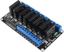
- 사용된 릴레이가 최대 부하 전류를 처리할 수 있는지 확인하세요.
- 단락을 피하기 위해 배선에 주의하세요.
- 일반적인 문제로는 플로팅 입력이 있습니다. 모든 연결이 안전한지 확인하세요.
- 장시간 사용 중 센서의 과열을 모니터링하세요.
필요한 구성 요소
- ACS758 전류 센서
- 12V 100A 릴레이
- I2C가 있는 LCD1602(4선)
- 2N2222 또는 2N3904 트랜지스터
- 1k 옴 1/4W 또는 모든 전력 저항
- 릴레이용 전원 공급 장치
- 부하용 전원 공급 장치
- 브레드보드
- 점퍼 와이어
배선 지침

Allegro ACS758 전류 센서와 LCD1602 디스플레이를 배선하려면 먼저 ACS758 센서를 연결하세요. 센서의 VCC 핀을 Arduino의 5V 핀에 연결합니다. GND 핀은 Arduino의 접지 핀에 연결해야 합니다. 센서의 S(신호) 핀은 Arduino의 아날로그 입력 핀 A0에 연결해야 합니다.
다음으로 LCD1602의 경우 VCC 핀을 Arduino의 5V 핀에 연결하고 GND 핀을 접지에 연결합니다. LCD의 SDA 핀은 Arduino의 A4 핀(SDA)에 연결하고, SCL 핀은 Arduino의 A5 핀(SCL)에 연결해야 합니다. 마지막으로 전류 값에 따라 부하를 제어하기 위해 릴레이 모듈을 디지털 핀 2에 연결합니다.
코드 예제 및 설명
Arduino 코드에서 ACS758 센서에 연결된 아날로그 입력 핀을 나타내는 VIN과 같은 주요 식별자를 정의하는 것으로 시작합니다. relayPin은 릴레이 제어를 위해 설정되고, maxCurrent는 과전류 보호의 임계값을 정의합니다.
#define VIN A0 // Arduino 핀 A0을 전압 입력(V in)으로 정의
const int relayPin = 2; // 릴레이용 디지털 핀 설정
const float maxCurrent = 15.00; // 최대 전류 설정
setup() 함수는 LCD를 초기화하고 릴레이 핀을 출력으로 설정합니다. 또한 LCD에 환영 메시지를 출력하여 사용 중인 전류 센서에 대해 알려줍니다.
void setup() {
    pinMode(relayPin, OUTPUT); // relayPin을 출력으로 설정
    Serial.begin(9600); // 시리얼 모니터 초기화
    lcd.begin(); // LCD 초기화
    lcd.backlight(); // 백라이트 켜기
    lcd.print("Robojax");
}
loop() 함수에서 센서의 전압을 지속적으로 읽고 전류를 계산합니다. 전류가 최대 한계를 초과하면 릴레이가 활성화되어 부하를 차단합니다. 이 로직은 시스템이 과전류 조건으로부터 스스로를 보호하도록 보장합니다.
void loop() {
  float voltage_raw = (5.0 / 1023.0) * analogRead(VIN); // 센서에서 전압 읽기
  float current = voltage / FACTOR; // 전류 계산
  if (current >= minCurrent) {
    if (current <= maxCurrent) {
      digitalWrite(relayPin, LOW); // 전류를 허용하려면 릴레이 OFF
    } else {
      digitalWrite(relayPin, HIGH); // 전류를 차단하려면 릴레이 ON
    }
  }
}
시연 / 기대 효과
모든 것이 배선되고 코드가 업로드되면 LCD에 현재 측정값이 표시됩니다. 전류가 정의된 maxCurrent를 초과하면 릴레이가 작동하여 부하를 차단합니다. 부하 전류를 점차 증가시키면서 LCD와 시리얼 모니터의 변화를 관찰하여 이를 테스트할 수 있습니다. 역극성 연결은 구성 요소를 손상시킬 수 있으므로(영상 10:15 부분) 반드시 피하십시오.
이미지


/*
 *
 * Arduino Sketch for Allegro ACS758 Current Sensor with LCD1602 & I2C module and current protection
 * This sensor can measure current at a range of up to 200A. It has overcurrent protection with a relay to disconnect the load if
 * the current reaches beyond the limit.
 * It operates with 3.3V or 5V.
 * This sketch requires you to watch the following 2 videos before using this code:
 * 1- ACS758 Sensor https://www.youtube.com/watch?v=SiHfjzcqnU4
 * 2- LCD1602 with I2C https://www.youtube.com/watch?v=q9YC_GVHy5A
 * 3- Combined 1 and 2 in one video https://www.youtube.com/watch?v=tug9wjCwDQA
 * 4- Allegro ACS with Robojax Library (latest video and code) https://youtu.be/sB6EULTix2k
 *
 * Written by Ahmad Shamshiri on Tuesday, June 26, 2018 at 17:56 in Ajax, Ontario, Canada
 * for Robojax.com
 * You can watch a detailed video on the ACS758 Current sensor at: https://youtu.be/SiHfjzcqnU4
 * This code has been explained in this video: https://youtu.be/GE4I10IZ1jY
 * This code has been downloaded from Robojax.com
 */
#define VIN A0 // define the Arduino pin A0 as voltage input (V in)
const int relayPin = 2;// set a digital pin for relay
const float VCC   = 5.0;// supply voltage 5V or 3.3V. If using PCB, set to 5V only.
const int model = 2;   // enter the model (see below)

const float maxCurrent = 15.00;// set maximum Current
int maxCurrentWait = 6000;// wait time before current is connected

float minCurrent = 1.00;// reading cutt-off current. 1.00 is 1 Amper

/*
          "ACS758LCB-050B",// for model use 0
          "ACS758LCB-050U",// for model use 1
          "ACS758LCB-100B",// for model use 2
          "ACS758LCB-100U",// for model use 3
          "ACS758KCB-150B",// for model use 4
          "ACS758KCB-150U",// for model use 5
          "ACS758ECB-200B",// for model use 6
          "ACS758ECB-200U"// for model use  7
The sensitivity array holds the sensitivity of the ACS758
current sensors. Do not change.
*/
float sensitivity[] ={
          40.0,// for ACS758LCB-050B
          60.0,// for ACS758LCB-050U
          20.0,// for ACS758LCB-100B
          40.0,// for ACS758LCB-100U
          13.3,// for ACS758KCB-150B
          16.7,// for ACS758KCB-150U
          10.0,// for ACS758ECB-200B
          20.0,// for ACS758ECB-200U
         };

/*
 *   Quiescent output voltage is a factor of VCC that appears at the output
 *   when the current is zero.
 *   For bidirectional sensors it is 0.5 x VCC
 *   For unidirectional sensors it is 0.12 x VCC
 *   For model ACS758LCB-050B, the B at the end represents Bidirectional (polarity doesn't matter)
 *   For model ACS758LCB-100U, the U at the end represents Unidirectional (polarity must match)
 *    Do not change.
 */
float quiescent_Output_voltage [] ={
          0.5,// for ACS758LCB-050B
          0.12,// for ACS758LCB-050U
          0.5,// for ACS758LCB-100B
          0.12,// for ACS758LCB-100U
          0.5,// for ACS758KCB-150B
          0.12,// for ACS758KCB-150U
          0.5,// for ACS758ECB-200B
          0.12,// for ACS758ECB-200U
          };
const float FACTOR = sensitivity[model]/1000;// set sensitivity for selected model
const float QOV =   quiescent_Output_voltage [model] * VCC;// set quiescent Output voltage for selected model
float voltage;// internal variable for voltage


// ======== start of LCD1602 with i2C settings
#include <Wire.h>
#include <LiquidCrystal_I2C.h>

// Set the LCD address to 0x27 for a 16 chars and 2 line display
LiquidCrystal_I2C lcd(0x27, 16, 2);
// ======= END of  LCD1602 with i2C settings
void setup() {
    //Robojax.com ACS758 Current Sensor
    pinMode(relayPin,OUTPUT);// set relayPin as output
    Serial.begin(9600);// initialize serial monitor
    Serial.println("Robojax Tutorial");
    Serial.println("ACS758 Current Sensor");
    Serial.println("with LCD1602 & I2C");
    // initialize the LCD,
    lcd.begin();
  // Turn on the blacklight and print a message.
  lcd.backlight();
    lcd.clear();
  lcd.print("Robojax");
  lcd.setCursor (0,1); // go to start of 2nd line
  lcd.print("ACS758 Current Sensor");
  delay(2000);
  lcd.clear();
}

void loop() {
  //Robojax code ACS758 with LCD1602 and I2C
  float voltage_raw =   (5.0 / 1023.0)* analogRead(VIN);// Read the voltage from sensor
  voltage =  voltage_raw - QOV + 0.007 ;// 0.007 is a value to make voltage zero when there is no current
  float current = voltage / FACTOR;
  if( current >= minCurrent){
     if(current <= maxCurrent)
     {
              Serial.print("Current Limit: ");
              Serial.print(maxCurrent,3);// print voltage with 3 decimal places
              Serial.print("A, I: ");
              Serial.print(current,2); // print the current with 2 decimal places
              Serial.println("A");
              //start of loop Robojax code ACS758 with LCD1602 and I2C
              lcd.clear();
              lcd.setCursor (0,0); // set to line 1, char 0
              lcd.print("Current: ");
              lcd.setCursor (9,0); // go to start of 2nd line
              lcd.print(current);
              lcd.setCursor (15,0); // go to start of 2nd line
              lcd.print("A");

              lcd.setCursor (0,1);
              lcd.print("I Limit: ");
              lcd.setCursor (9,1); // go to start of 2nd line
              lcd.print(maxCurrent);
              lcd.setCursor (15,1); // go to start of 2nd line
              lcd.print("A");
              lcd.backlight();
             //end of loopcode Robojax code ACS758 with LCD1602 and I2C

              digitalWrite(relayPin,LOW);// turn the relay OFF to allow the current.
     }else{
      // the lines bellow will execute if current reaches above the maxCurrent value
              digitalWrite(relayPin,HIGH);// turn the relay ON to disconnect the current.

              Serial.print("Max Reached:");
              Serial.print(maxCurrent,3);// print the maxCurrent
              Serial.println("A");
              Serial.print("Disconnected ");

              //start of loop Robojax code ACS758 with LCD1602 and I2C
              lcd.clear();
              lcd.setCursor (0,0); // set to line 1, char 0
              lcd.print("I Max: ");
              lcd.setCursor (8,0); // go to start of 2nd line
              lcd.print(maxCurrent);
              lcd.setCursor (15,0); // go to start of 2nd line
              lcd.print("A");

              lcd.setCursor (0,1);
              lcd.print("Disconnected");
              lcd.backlight();
             //end of loopcode Robojax code ACS758 with LCD1602 and I2C
             delay(maxCurrentWait );// wait for maxCurrentWait  seconds
     }

  }else{
    Serial.println("No Current");
  lcd.clear();
  lcd.setCursor (0,0);
  lcd.print("No Current");
  digitalWrite(relayPin,LOW);// turn the relay OFF to allow the current.

  }
  delay(500);
}
필요할 수 있는 것들
-
아마존
-
아마존
-
아마존
-
알리익스프레스Purchase 10pcs LCD1602-I2C from AliExpresss.click.aliexpress.com
-
알리익스프레스Purchase an LCD1602 from AliExpresss.click.aliexpress.com
-
방굿Purchase LCD1602 display from Banggoodbanggood.com
자원 및 참고자료
-
외부Purchase an LCD1602 from AliExpresss.click.aliexpress.com
-
외부
-
외부
-
외부
-
외부Purchase LCD1602 display from Banggoodbanggood.com
파일📁
데이터시트 (pdf)
-
ACS758 current sensor datasheet
robojax_ACS758_current_sensor_datasheet.pdf1.03 MB