Sensor de corriente Allegro ACS758 con pantalla LCD y protección contra sobrecorriente para Arduino
En este tutorial aprenderemos a utilizar el sensor de corriente Allegro ACS758 con una pantalla LCD para mostrar las lecturas de corriente e implementar protección contra sobrecorriente. Esta configuración nos permite monitorizar la corriente y desconectar la carga automáticamente si supera un límite predefinido. El proyecto combina componentes de hardware y software para crear un sistema funcional de monitorización de corriente.

Siguiendo esta guía, podrá cablear los componentes correctamente y comprender la lógica de programación detrás del código. Para una explicación más visual, asegúrese de ver el video asociado (a las 00:00).
Hardware explicado
Los componentes clave de este proyecto incluyen el sensor de corriente Allegro ACS758, una pantalla LCD1602 con interfaz I2C y una placa Arduino. El sensor ACS758 mide la corriente que fluye a través de él y proporciona una tensión proporcional a la corriente. La pantalla LCD1602 muestra las lecturas de corriente y mensajes de estado, mientras que la placa Arduino procesa los datos y controla el relé para la protección contra sobrecorriente.
El sensor ACS758 funciona según un principio llamado detección por efecto Hall, que le permite medir la corriente sin contacto eléctrico directo. El voltaje de salida cambia en función de la cantidad de corriente que lo atraviesa, proporcionando una forma segura y eficiente de monitorear las cargas eléctricas.
Detalles de la ficha técnica
| Fabricante | Allegro MicroSystems |
|---|---|
| Número de pieza | ACS758 |
| Tensión lógica/E/S | 3.3V / 5V |
| Tensión de alimentación | 5 V |
| Corriente de salida (por canal) | 200 A máx. |
| Corriente de pico (por canal) | 200A |
| Guía de frecuencia PWM | N/D |
| Umbrales lógicos de entrada | 0.5 x VCC (bidireccional) |
| Caída de tensión / RDS(on) / saturación | No aplica |
| Límites térmicos | 150 °C |
| Paquete | Montaje en PCB |
| Notas / variantes | Varios modelos disponibles para distintos rangos de corriente |
- Asegúrese de una disipación de calor adecuada si opera cerca de las especificaciones máximas.
- Utilice condensadores de desacoplo para estabilizar la tensión de la fuente de alimentación.
- Verifique que el relé utilizado pueda soportar la corriente máxima de la carga.
- Tenga cuidado con el cableado para evitar cortocircuitos.
- Los errores comunes incluyen entradas flotantes; asegúrese de que todas las conexiones estén seguras.
- Controle el sobrecalentamiento del sensor durante un uso prolongado.
Componentes necesarios
- sensor de corriente ACS758
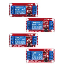
- relé 12 V 100 A
- LCD1602 con I2C (4 hilos)
- Transistor 2N2222 o 2N3904
- 1 kΩ 1/4 W o cualquier resistencia de potencia
- Fuente de alimentación para relé
- Fuente de alimentación para su carga
- placa de pruebas
- Cables de puente
Instrucciones de cableado

Para cablear el sensor de corriente Allegro ACS758 y la pantalla LCD1602, comience conectando el sensor ACS758. Conecte elVCCpin del sensor al pin de 5V del Arduino. ElGNDel pin debe conectarse a un pin de tierra del Arduino. ElSEl pin (de señal) del sensor debe conectarse al pin de entrada analógica.A0en el Arduino.
A continuación, para el LCD1602, conecta elVCCpin al pin de 5V del Arduino y elGNDfijar al suelo. ElSDAel pin del LCD debería conectarse aA4pin (SDA) en el Arduino, mientras que elSCLel pin debería conectarse aA5pin (SCL) del Arduino. Finalmente, conecta un módulo de relé al pin digital2para controlar la carga en función de las lecturas de corriente.
Ejemplos de código y guía paso a paso
En el código de Arduino, empezamos por definir identificadores clave comoVIN, que representa el pin de entrada analógica conectado al sensor ACS758. ElrelayPinestá configurado para el control del relé, mientras quemaxCurrentdefine el umbral para la protección contra sobrecorriente.
#define VIN A0 // define the Arduino pin A0 as voltage input (V in)
const int relayPin = 2; // set a digital pin for relay
const float maxCurrent = 15.00; // set maximum Current
Elsetup()La función inicializa la LCD y configura el pin del relé como salida. Además, imprime un mensaje de bienvenida en la LCD, informando al usuario sobre el sensor de corriente que se está utilizando.
void setup() {
    pinMode(relayPin, OUTPUT); // set relayPin as output
    Serial.begin(9600); // initialize serial monitor
    lcd.begin(); // initialize the LCD
    lcd.backlight(); // Turn on the blacklight
    lcd.print("Robojax");
}
En elloop()función, leemos continuamente el voltaje del sensor y calculamos la corriente. Si la corriente supera el límite máximo, se activa el relé para desconectar la carga. Esta lógica garantiza que el sistema se proteja de condiciones de sobrecorriente.
void loop() {
  float voltage_raw = (5.0 / 1023.0) * analogRead(VIN); // Read the voltage from sensor
  float current = voltage / FACTOR; // Calculate current
  if (current >= minCurrent) {
    if (current <= maxCurrent) {
      digitalWrite(relayPin, LOW); // turn the relay OFF to allow current
    } else {
      digitalWrite(relayPin, HIGH); // turn the relay ON to disconnect current
    }
  }
}
Demostración / Qué esperar
Una vez que todo esté cableado y el código cargado, la pantalla LCD mostrará las lecturas de corriente actuales. Si la corriente supera el valor definidomaxCurrent, el relé se activará, desconectando la carga. Puedes comprobar esto aumentando gradualmente la corriente de carga y observando los cambios en la pantalla LCD y en el monitor serial. Asegúrate de evitar conexiones con polaridad invertida, ya que esto puede dañar los componentes (en el video a 10:15).
Imágenes


/*
 *
 * Arduino Sketch for Allegro ACS758 Current Sensor with LCD1602 & I2C module and current protection
 * This sensor can measure current at a range of up to 200A. It has overcurrent protection with a relay to disconnect the load if
 * the current reaches beyond the limit.
 * It operates with 3.3V or 5V.
 * This sketch requires you to watch the following 2 videos before using this code:
 * 1- ACS758 Sensor https://www.youtube.com/watch?v=SiHfjzcqnU4
 * 2- LCD1602 with I2C https://www.youtube.com/watch?v=q9YC_GVHy5A
 * 3- Combined 1 and 2 in one video https://www.youtube.com/watch?v=tug9wjCwDQA
 * 4- Allegro ACS with Robojax Library (latest video and code) https://youtu.be/sB6EULTix2k
 *
 * Written by Ahmad Shamshiri on Tuesday, June 26, 2018 at 17:56 in Ajax, Ontario, Canada
 * for Robojax.com
 * You can watch a detailed video on the ACS758 Current sensor at: https://youtu.be/SiHfjzcqnU4
 * This code has been explained in this video: https://youtu.be/GE4I10IZ1jY
 * This code has been downloaded from Robojax.com
 */
#define VIN A0 // define the Arduino pin A0 as voltage input (V in)
const int relayPin = 2;// set a digital pin for relay
const float VCC   = 5.0;// supply voltage 5V or 3.3V. If using PCB, set to 5V only.
const int model = 2;   // enter the model (see below)

const float maxCurrent = 15.00;// set maximum Current
int maxCurrentWait = 6000;// wait time before current is connected

float minCurrent = 1.00;// reading cutt-off current. 1.00 is 1 Amper

/*
          "ACS758LCB-050B",// for model use 0
          "ACS758LCB-050U",// for model use 1
          "ACS758LCB-100B",// for model use 2
          "ACS758LCB-100U",// for model use 3
          "ACS758KCB-150B",// for model use 4
          "ACS758KCB-150U",// for model use 5
          "ACS758ECB-200B",// for model use 6
          "ACS758ECB-200U"// for model use  7
The sensitivity array holds the sensitivity of the ACS758
current sensors. Do not change.
*/
float sensitivity[] ={
          40.0,// for ACS758LCB-050B
          60.0,// for ACS758LCB-050U
          20.0,// for ACS758LCB-100B
          40.0,// for ACS758LCB-100U
          13.3,// for ACS758KCB-150B
          16.7,// for ACS758KCB-150U
          10.0,// for ACS758ECB-200B
          20.0,// for ACS758ECB-200U
         };

/*
 *   Quiescent output voltage is a factor of VCC that appears at the output
 *   when the current is zero.
 *   For bidirectional sensors it is 0.5 x VCC
 *   For unidirectional sensors it is 0.12 x VCC
 *   For model ACS758LCB-050B, the B at the end represents Bidirectional (polarity doesn't matter)
 *   For model ACS758LCB-100U, the U at the end represents Unidirectional (polarity must match)
 *    Do not change.
 */
float quiescent_Output_voltage [] ={
          0.5,// for ACS758LCB-050B
          0.12,// for ACS758LCB-050U
          0.5,// for ACS758LCB-100B
          0.12,// for ACS758LCB-100U
          0.5,// for ACS758KCB-150B
          0.12,// for ACS758KCB-150U
          0.5,// for ACS758ECB-200B
          0.12,// for ACS758ECB-200U
          };
const float FACTOR = sensitivity[model]/1000;// set sensitivity for selected model
const float QOV =   quiescent_Output_voltage [model] * VCC;// set quiescent Output voltage for selected model
float voltage;// internal variable for voltage


// ======== start of LCD1602 with i2C settings
#include <Wire.h>
#include <LiquidCrystal_I2C.h>

// Set the LCD address to 0x27 for a 16 chars and 2 line display
LiquidCrystal_I2C lcd(0x27, 16, 2);
// ======= END of  LCD1602 with i2C settings
void setup() {
    //Robojax.com ACS758 Current Sensor
    pinMode(relayPin,OUTPUT);// set relayPin as output
    Serial.begin(9600);// initialize serial monitor
    Serial.println("Robojax Tutorial");
    Serial.println("ACS758 Current Sensor");
    Serial.println("with LCD1602 & I2C");
    // initialize the LCD,
    lcd.begin();
  // Turn on the blacklight and print a message.
  lcd.backlight();
    lcd.clear();
  lcd.print("Robojax");
  lcd.setCursor (0,1); // go to start of 2nd line
  lcd.print("ACS758 Current Sensor");
  delay(2000);
  lcd.clear();
}

void loop() {
  //Robojax code ACS758 with LCD1602 and I2C
  float voltage_raw =   (5.0 / 1023.0)* analogRead(VIN);// Read the voltage from sensor
  voltage =  voltage_raw - QOV + 0.007 ;// 0.007 is a value to make voltage zero when there is no current
  float current = voltage / FACTOR;
  if( current >= minCurrent){
     if(current <= maxCurrent)
     {
              Serial.print("Current Limit: ");
              Serial.print(maxCurrent,3);// print voltage with 3 decimal places
              Serial.print("A, I: ");
              Serial.print(current,2); // print the current with 2 decimal places
              Serial.println("A");
              //start of loop Robojax code ACS758 with LCD1602 and I2C
              lcd.clear();
              lcd.setCursor (0,0); // set to line 1, char 0
              lcd.print("Current: ");
              lcd.setCursor (9,0); // go to start of 2nd line
              lcd.print(current);
              lcd.setCursor (15,0); // go to start of 2nd line
              lcd.print("A");

              lcd.setCursor (0,1);
              lcd.print("I Limit: ");
              lcd.setCursor (9,1); // go to start of 2nd line
              lcd.print(maxCurrent);
              lcd.setCursor (15,1); // go to start of 2nd line
              lcd.print("A");
              lcd.backlight();
             //end of loopcode Robojax code ACS758 with LCD1602 and I2C

              digitalWrite(relayPin,LOW);// turn the relay OFF to allow the current.
     }else{
      // the lines bellow will execute if current reaches above the maxCurrent value
              digitalWrite(relayPin,HIGH);// turn the relay ON to disconnect the current.

              Serial.print("Max Reached:");
              Serial.print(maxCurrent,3);// print the maxCurrent
              Serial.println("A");
              Serial.print("Disconnected ");

              //start of loop Robojax code ACS758 with LCD1602 and I2C
              lcd.clear();
              lcd.setCursor (0,0); // set to line 1, char 0
              lcd.print("I Max: ");
              lcd.setCursor (8,0); // go to start of 2nd line
              lcd.print(maxCurrent);
              lcd.setCursor (15,0); // go to start of 2nd line
              lcd.print("A");

              lcd.setCursor (0,1);
              lcd.print("Disconnected");
              lcd.backlight();
             //end of loopcode Robojax code ACS758 with LCD1602 and I2C
             delay(maxCurrentWait );// wait for maxCurrentWait  seconds
     }

  }else{
    Serial.println("No Current");
  lcd.clear();
  lcd.setCursor (0,0);
  lcd.print("No Current");
  digitalWrite(relayPin,LOW);// turn the relay OFF to allow the current.

  }
  delay(500);
}
Cosas que podrías necesitar
-
Amazonas
-
Amazonas
-
Amazonas
-
AliExpressCompra un LCD1602 en AliExpresss.click.aliexpress.com
-
AliExpressComprar 10 piezas de LCD1602-I2C en AliExpresss.click.aliexpress.com
-
BanggoodCompra la pantalla LCD1602 de Banggood.banggood.com
Recursos y referencias
-
ExternoCompra la pantalla LCD1602 de Banggood.banggood.com
-
Externo
-
Externo
-
Externo
-
ExternoCompra un LCD1602 en AliExpresss.click.aliexpress.com
Archivos📁
Hoja de datos (pdf)
-
Hoja de datos del sensor de corriente ACS758
robojax_ACS758_current_sensor_datasheet.pdf1.03 MB