This tutorial is part of: Servo Motors
All videos related to servo motors that are related, listed here. Links to other videos are below this article.
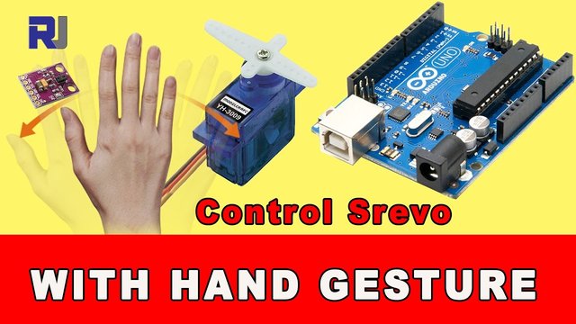
Controlling Servo Position with Hand Gestures for Arduino
In this tutorial, we will learn how to control a servo motor using hand gestures. By moving your hand left or right, you can make the servo motor respond accordingly. This project utilizes the APDS-9960 gesture sensor to detect hand movements and translate them into servo positions. For a detailed visual explanation, make sure to check the video at (in video at 00:30).

The core components we will be using include a servo motor and the APDS-9960 gesture sensor. The servo motor will rotate to specific angles based on the detected gestures, while the APDS-9960 sensor will interpret the hand movements. This setup allows for an intuitive way to control the servo without physical touch.
Hardware Explained
The servo motor is a small device that can rotate to specific angles, making it ideal for applications that require precise positioning. It typically has three wires: power (red), ground (black), and signal (orange). The signal wire receives commands to move the servo to a specified angle.
The APDS-9960 is a versatile sensor that can detect gestures, ambient light, and color. It communicates with the Arduino via I2C and requires a few pins for power and data transfer. The sensor can detect movements such as up, down, left, and right, which we will use to control the servo.
Datasheet Details
| Manufacturer | Broadcom |
|---|---|
| Part number | APDS-9960 |
| Logic/IO voltage | 2.4 – 3.6 V |
| Supply voltage | 2.4 – 3.6 V |
| Output current (per channel) | 20 mA max |
| PWM frequency guidance | Not applicable |
| Input logic thresholds | 0.3 V (low), 0.7 V (high) |
| Voltage drop / RDS(on) / saturation | Not applicable |
| Thermal limits | –40 to 85 °C |
| Package | 6.0 x 3.0 mm |
| Notes / variants | Gesture sensing, RGB light sensing |
- Ensure the servo is powered with adequate voltage (typically 5V).
- Connect the APDS-9960 to the Arduino using I2C communication.
- Pay attention to the interrupt pin for the gesture sensor.
- Use pull-up resistors if necessary for stable signal detection.
- Make sure to calibrate the sensor in different lighting conditions for better accuracy.

To wire the components, start with the servo motor. Connect the red wire to the Arduino's 5V pin, the black wire to the ground (GND), and the orange signal wire to pin 9. This will allow the Arduino to control the servo's position.
Next, wire the APDS-9960 gesture sensor. Connect the V_N pin to the Arduino's 3.3V, and the GND pin to ground. The INT pin should be connected to pin 2 on the Arduino, while the SDA and SCL pins go to pins A4 and A5, respectively. This configuration allows the sensor to communicate effectively with the Arduino.
Code Examples & Walkthrough
In the setup function, we initialize the servo and the gesture sensor. The line myservo.attach(9); binds the servo to pin 9, which we previously connected. This allows the servo to receive commands from the Arduino.

void setup() {
 myservo.attach(9);  // attaches the servo on pin 9 to the servo object
 // Set interrupt pin as input
 pinMode(APDS9960_INT, INPUT);
 // Initialize Serial port
 Serial.begin(9600);
}
Next, we define how the system handles gestures in the loop function. The method handleGesture(); checks for available gestures and executes corresponding actions. For instance, if the gesture detected is left, the servo will move to 180 degrees.
void handleGesture() {
    if ( apds.isGestureAvailable() ) {
    switch ( apds.readGesture() ) {
      case DIR_LEFT:
        myservo.write(180);  // added by RoboJax
        break;
      case DIR_RIGHT:
        myservo.write(0);   // added by RoboJax
        break;
    }
  }
}
Finally, the loop continuously checks for gestures and updates the servo position based on the detected gesture. Ensure to test the setup in various lighting conditions to get accurate gesture recognition.
Demonstration / What to Expect
Once everything is wired and the code is uploaded, you should be able to control the servo by moving your hand left or right. The servo will rotate to 180 degrees for a left gesture and return to 0 degrees for a right gesture. If the gestures are not detected, check the sensor's positioning and surrounding light conditions (in video at 05:30).
Chapters
- Introduction - 00:00
- Hardware Overview - 01:30
- Wiring Instructions - 03:00
- Code Explanation - 04:30
- Demonstration - 06:00
Images

This tutorial is part of: Servo Motors
- Controlling a Servo with Push Buttons Using Arduino
- Control a Servo Motor with a Push Button: Move Servo and Return SPB-1
- Control a Servo Motor with a Push Button: Move Servo in One Direction SPB-2
- Controlling a Servo Motor with a Push Button: Move Servo While Button Is Pressed (SPB-3)
- Controlling a Servo with a Potentiometer Using Arduino
- Controlling a Servo with Potentiometer and LCD1602 using Arduino
- Controlling Servo Motors Using an Infrared Remote with Arduino
- Arduino Servo Motor Control Using a Potentiometer
- Controlling Two or More Servos with Potentiometers Using an Arduino
- How to Control a 360° Servo with Three Push-Button Switches
- How to Use Continuous 360° Servo with Arduino
- Arduino Code and Video for PCA9685 16-Channel 12-Bit Servo Controller V1
- Build an Arduino Servo Toggle Switch with a Push Button
++
/****************************************************************
Modified for RoboJax by A.B.S. on May 09, 2017
in Ajax, Ontario, Canada. www.RoboJax.com


Original Source:
APDS-9960 RGB and Gesture Sensor
Shawn Hymel @ SparkFun Electronics
May 30, 2014
https://github.com/sparkfun/APDS-9960_RGB_and_Gesture_Sensor


Distributed as-is; no warranty is given.
****************************************************************/

#include <Wire.h>

// added by RoboJax
#include <Servo.h>

#include <SparkFun_APDS9960.h>


Servo myservo;  // create servo object to control a servo // added by RoboJax

// Pins
#define APDS9960_INT    2 // Needs to be an interrupt pin

// Constants

// Global Variables
SparkFun_APDS9960 apds = SparkFun_APDS9960();
int isr_flag = 0;

void setup() {
 myservo.attach(9);  // attaches the servo on pin 9 to the servo object
  // Set interrupt pin as input
  pinMode(APDS9960_INT, INPUT);

  // Initialize Serial port
  Serial.begin(9600);
  Serial.println();
  Serial.println(F("--------------------------------"));
  Serial.println(F("SparkFun APDS-9960 - GestureTest"));
  Serial.println(F("--------------------------------"));

  // Initialize interrupt service routine
  attachInterrupt(0, interruptRoutine, FALLING);

  // Initialize APDS-9960 (configure I2C and initial values)
  if ( apds.init() ) {
    Serial.println(F("APDS-9960 initialization complete"));
  } else {
    Serial.println(F("Something went wrong during APDS-9960 init!"));
  }

  // Start running the APDS-9960 gesture sensor engine
  if ( apds.enableGestureSensor(true) ) {
    Serial.println(F("Gesture sensor is now running"));
  } else {
    Serial.println(F("Something went wrong during gesture sensor init!"));
  }
}

void loop() {
  if( isr_flag == 1 ) {
    detachInterrupt(0);
    handleGesture();
    isr_flag = 0;
    attachInterrupt(0, interruptRoutine, FALLING);
  }
}

void interruptRoutine() {
  isr_flag = 1;
}

void handleGesture() {
    if ( apds.isGestureAvailable() ) {
    switch ( apds.readGesture() ) {
      case DIR_UP:
        Serial.println("UP");
        break;
      case DIR_DOWN:
        Serial.println("DOWN");
        break;
      case DIR_LEFT:
        Serial.println("LEFT");
        myservo.write(180);  // added by RoboJax
        break;
      case DIR_RIGHT:
        Serial.println("RIGHT");
        myservo.write(0);   // added by RoboJax
        break;
      case DIR_NEAR:
        Serial.println("NEAR");
        break;
      case DIR_FAR:
        Serial.println("FAR");
        break;
      default:
        Serial.println("NONE");
    }
  }
}
Resources & references
No resources yet.
Files📁
No files available.