Measuring Current Using an Allegro ACS758 Current Sensor with an LCD1602 (I2C) for Arduino
In this tutorial, we will learn how to measure current using the Allegro ACS758 current sensor and display the readings on an LCD1602 using I2C communication. This setup is useful for various applications, such as monitoring power consumption in circuits or managing battery usage in devices. By the end of this project, you will have a functioning system that displays real-time current readings.


The ACS758 current sensor can measure currents up to 200A, making it ideal for high-power applications. The LCD1602 display will show the current in amperes along with the corresponding voltage sensed by the current sensor. To clarify any steps, be sure to check the video (in video at 00:00) for a visual demonstration.
Hardware Explained
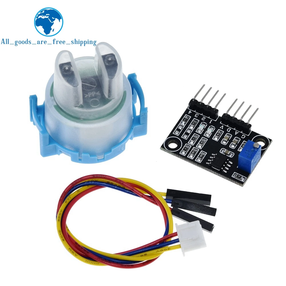
The main components of this project include the Allegro ACS758 current sensor and the LCD1602 display with I2C. The ACS758 operates by measuring the magnetic field generated by the current flowing through a conductor. It provides an output voltage proportional to the current flowing, which can be easily read by the Arduino.
The LCD1602 is a 16x2 character display that uses I2C communication, allowing for easy connection and control with only two data pins. This reduces the number of wires needed, simplifying the wiring process. The I2C interface enables multiple devices to communicate over the same bus, making it a versatile choice for projects.
Datasheet Details
| Manufacturer | Allegro Microsystems |
|---|---|
| Part number | ACS758 |
| Logic/IO voltage | 3.3V / 5V |
| Supply voltage | 5V |
| Output current (per channel) | 200 A max |
| Peak current (per channel) | 200 A |
| PWM frequency guidance | N/A |
| Input logic thresholds | 0.3V (low), 2.7V (high) |
| Voltage drop / RDS(on) / saturation | 0.5V max |
| Thermal limits | up to 150°C |
| Package | TO-220 |
| Notes / variants | Bidirectional and unidirectional options |
- Ensure proper heat sinking for high current applications.
- Decouple the power supply to avoid noise affecting readings.
- Use twisted pair wires for the current path to minimize interference.
- Verify the output voltage corresponding to zero current for calibration.
- Check polarity when using unidirectional sensors.
Wiring Instructions

To wire the Allegro ACS758 current sensor and the LCD1602 display, start by connecting the power and ground. Connect the VCC pin of the ACS758 to the 5V pin on the Arduino, and connect the GND pin to the Arduino’s ground. The signal output pin (Vout) from the ACS758 should be connected to the analog input pin A0 on the Arduino.
Next, for the LCD1602 display, connect the VCC pin to the 5V pin on the Arduino and the GND pin to ground. The SDA (data line) from the LCD should connect to the Arduino's A4 pin, and the SCL (clock line) should connect to the A5 pin. This setup allows for I2C communication between the Arduino and the LCD1602.
Code Examples & Walkthrough
The Arduino sketch begins by defining the input pin for the current sensor. The variable VIN is defined as A0, which is where the sensor's output will be read. The voltage supply and model of the ACS758 are also defined. The sensitivity for the selected model is calculated using the sensitivity array.
#define VIN A0 // define the Arduino pin A0 as voltage input (V in)
const float VCC = 5.0; // supply voltage 5V or 3.3V
const int model = 2; // enter the model (see below)
In the setup() function, the LCD is initialized and a welcome message is displayed. The backlight is turned on for better visibility. This is where you can customize the initial display message to suit your project.
void setup() {
    Serial.begin(9600); // initialize serial monitor
    lcd.begin(); // initialize the LCD
    lcd.backlight();
    lcd.print("Robojax");
    lcd.setCursor (0,1); // go to start of 2nd line
    lcd.print("ACS758 Current Sensor");
    delay(2000); // delay for 2 seconds
    lcd.clear();
}
In the loop() function, the voltage from the sensor is read and processed to calculate the current. If the voltage exceeds a defined cutoff limit, the current is displayed on both the serial monitor and the LCD. If no current is detected, a message is shown indicating "No Current". This allows for real-time monitoring of current flow.
void loop() {
  float voltage_raw = (5.0 / 1023.0) * analogRead(VIN); // Read voltage from sensor
  float current = voltage / FACTOR;
  if (abs(voltage) > cutOff) {
    Serial.print("V: "); Serial.print(voltage, 3); // print voltage
    lcd.print(current); // display current on LCD
  } else {
    Serial.println("No Current"); // output when no current is detected
  }
  delay(500); // wait before next reading
}
Make sure to watch the full code walkthrough in the video (in video at 01:30) for a detailed explanation of each segment.
Demonstration / What to Expect
When powered on, the system will display the current flowing through the sensor on the LCD in real-time. You can test the setup by applying a known current and observing the readings. If the sensor detects current, the voltage and current values will update on the display. If there is no current, the message "No Current" will appear. Be cautious of reversed polarity connections, which can lead to incorrect readings or damage to the components.
图像


This code has not been parsed yet. Please return to the admin panel to parse it.|||您可能需要的东西
-
亚马逊亚马逊上的ACS758电流传感器amzn.to
-
易趣从eBay购买Allegro ACS758电流传感器ebay.us
-
全球速卖通从AliExpress购买Allegro ACS758电流传感器s.click.aliexpress.com
资源与参考
尚无可用资源。
文件📁
Fritzing 文件
-
LCD LCD1602-I2C module with 4 wires
LCD1602-I2C.fzpz0.01 MB