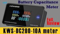
Review of KWS-DC200-10A 0-200V DC Energy, Power, Capacity Volt Ammeter Calibration
This guide provides a comprehensive review and teardown of the KWS-DC200-10A, a digital multifunction DC energy meter. This device is a versatile tool for any electronics workbench, enabling you to monitor voltage, current, power, energy consumption, and temperature in a single, panel-mounted unit. Beyond simple measurement, it's an invaluable asset for a variety of practical projects.
Here are a few ways you can put this meter to use:
- Monitoring Battery Banks: For off-grid solar or backup power systems, this meter can track the state of charge and health of a 12V or 24V battery bank in real-time.
- Building a Power Consumption Logger: Use it to measure the energy draw of a specific device or circuit over time (in watt-hours) to understand its efficiency.
- Creating a Bench Power Supply Display: Integrate it into a DIY variable power supply to provide a clear, accurate readout of the output voltage and current.
- Developing a Battery Capacity Tester: By pairing it with a constant current load, you can use the meter's amp-hour (Ah) counting feature to measure the true capacity of batteries like 18650 cells or lead-acid batteries.
- Temperature Monitoring: The included thermistor allows you to monitor the temperature of heatsinks, batteries, or enclosures, making it perfect for a high-power project that needs thermal management.
Hardware Overview
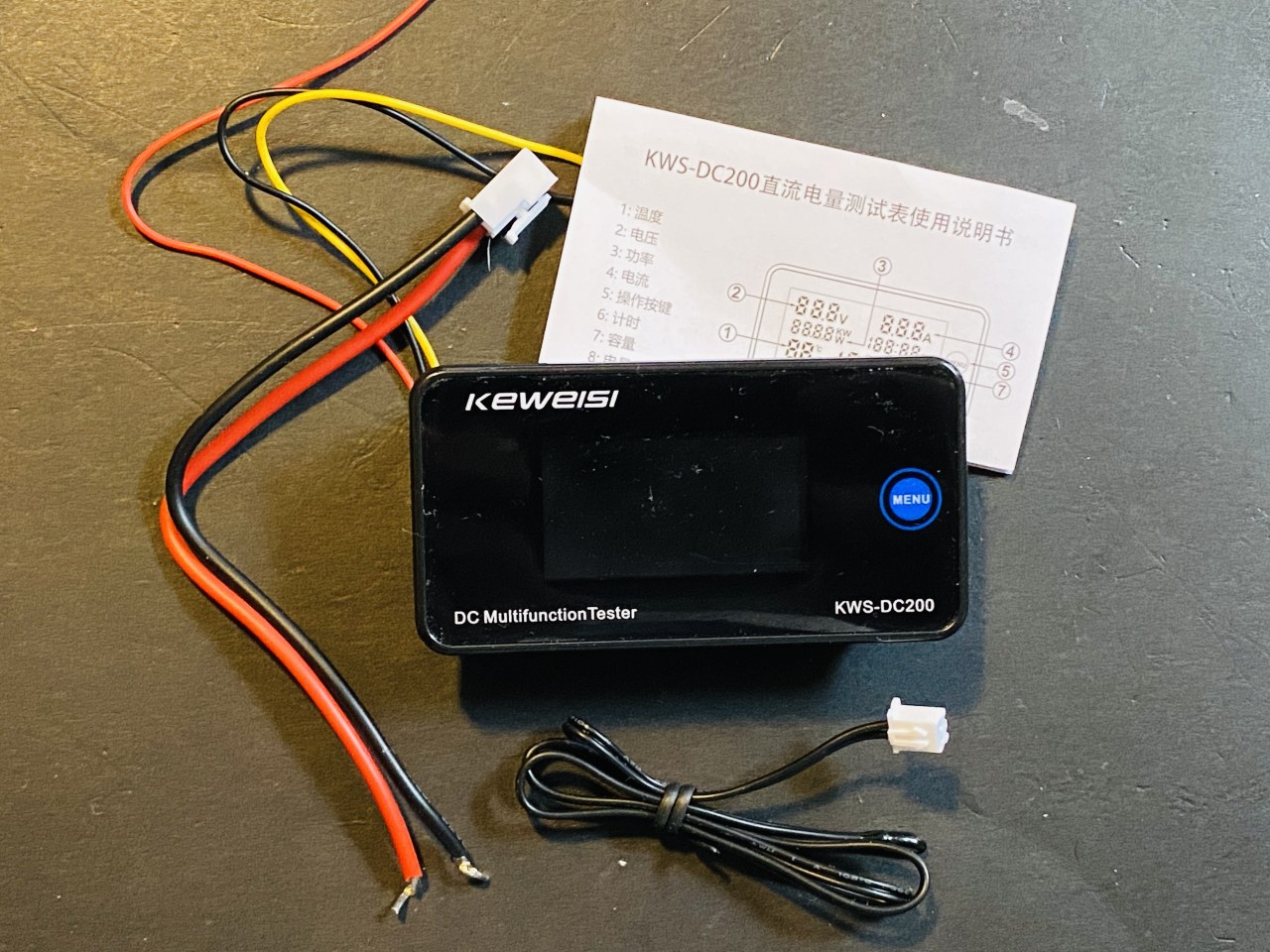
The KWS-DC200-10A is a compact, panel-mount digital meter. The review unit is the 10-ampere version, which uses an internal shunt resistor for current sensing. The package includes the meter itself, a user manual with detailed wiring diagrams, and a thermistor for temperature readings. The unit is powered by a separate 8-120V DC supply, while it can measure a system voltage of 0-200V DC. This separation allows for flexibility, especially when measuring low voltages.
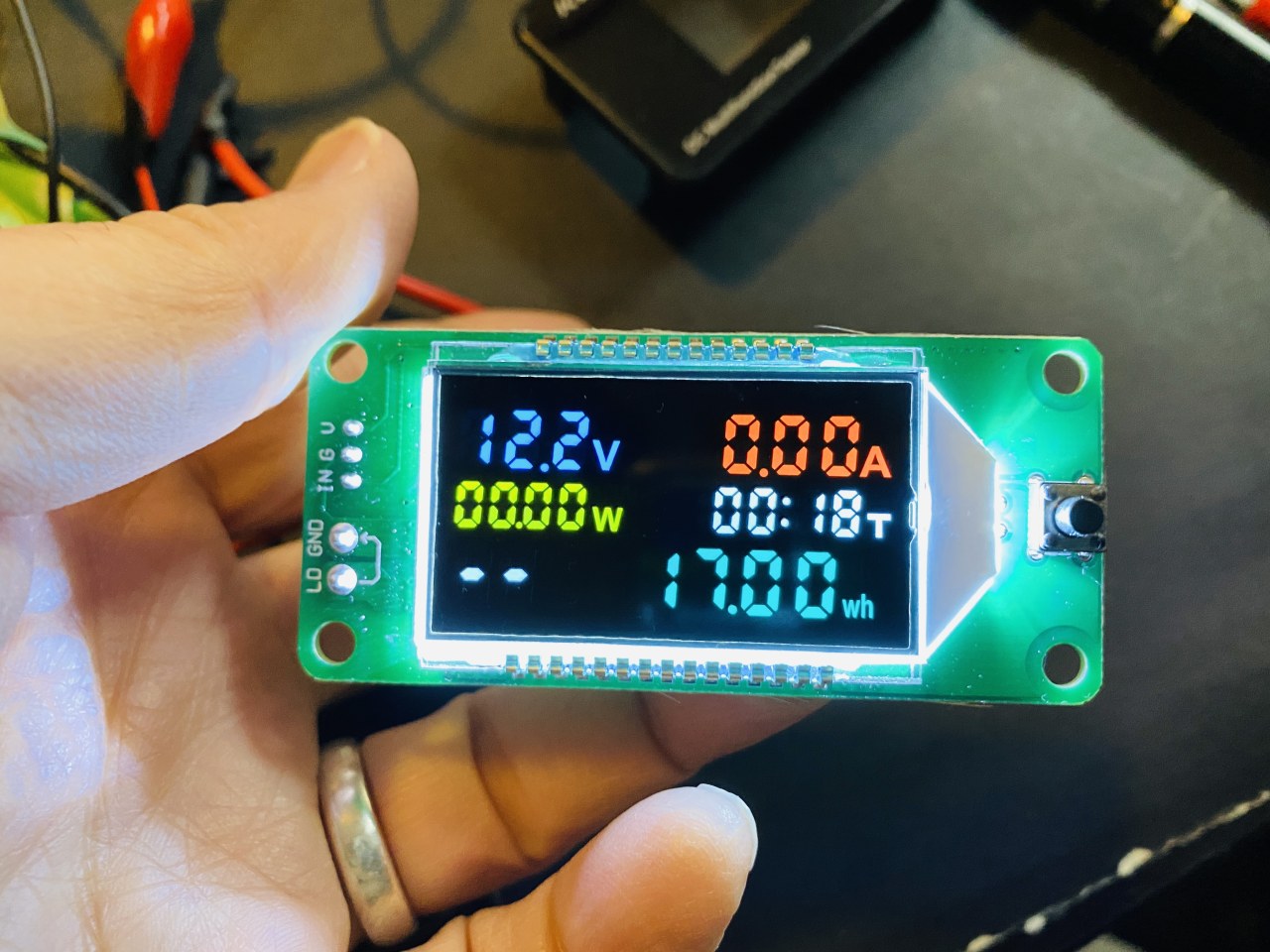
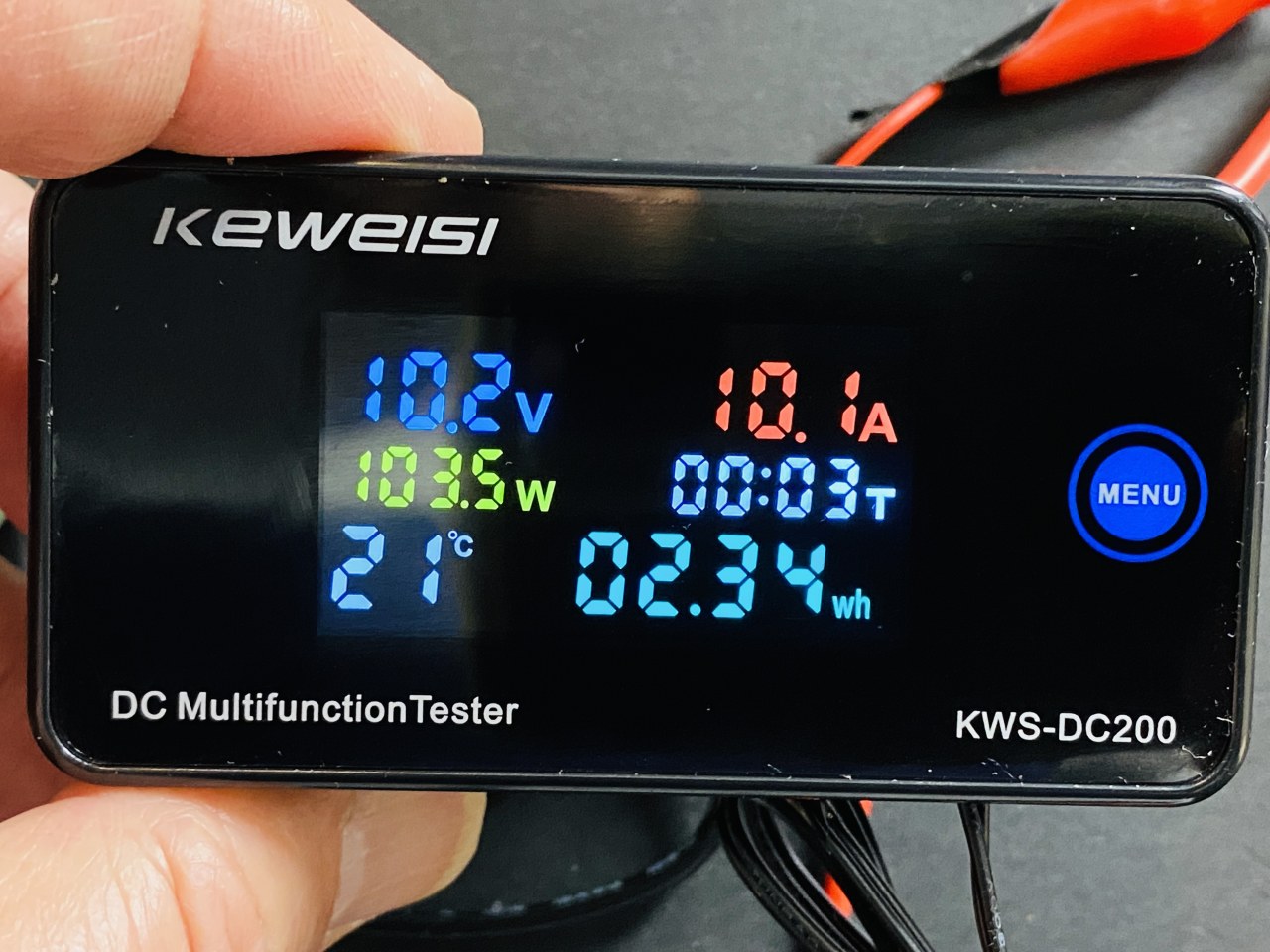
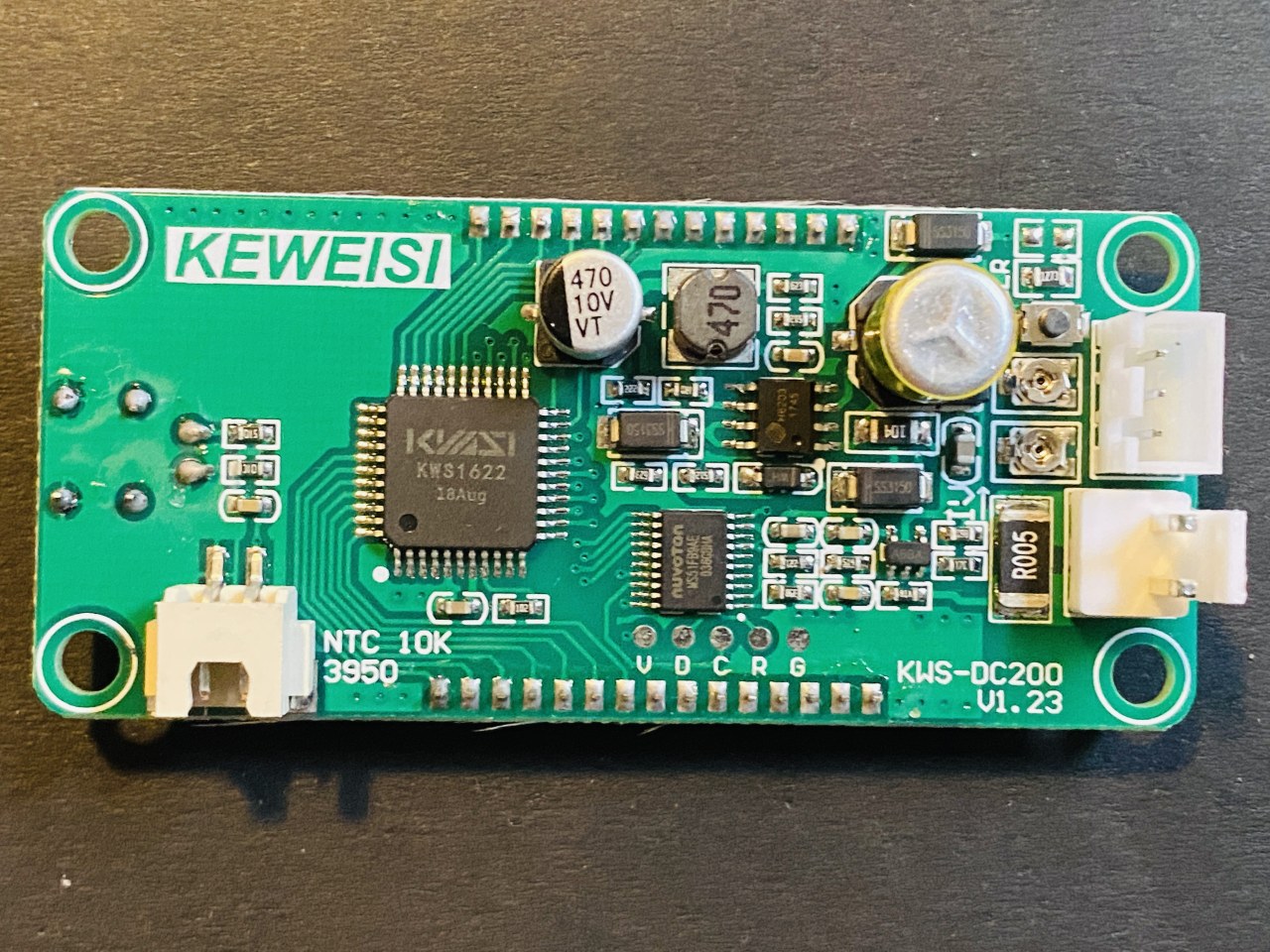
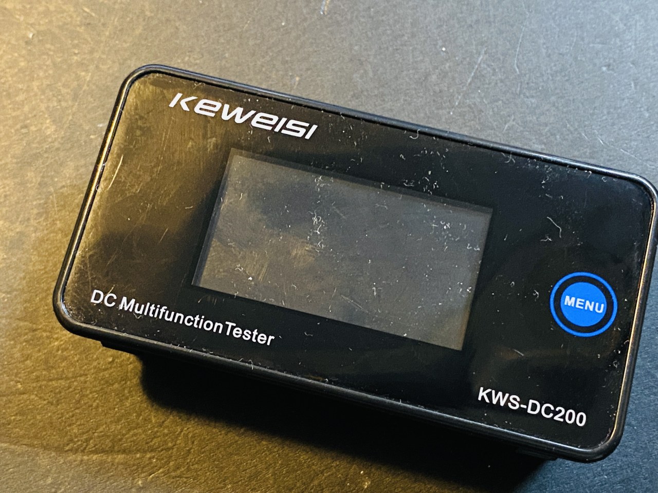
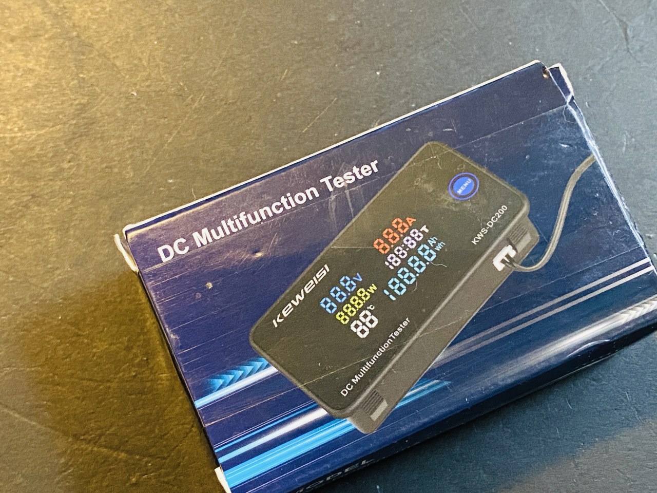
On the front, a bright LED display shows all the key metrics: Voltage (V), Current (A), Power (W), Energy (Wh), Capacity (Ah), and Temperature (°C). A single push button on the front cycles through the different display modes. On the back, you'll find the main power/measurement terminals, a connector for the thermistor, and two small potentiometers for calibrating the voltage and current readings. There is also a reset button, though its functionality was found to be inconsistent in this review unit.
Wiring Guide
The wiring for this meter is straightforward but has a few important configurations depending on your setup. The meter has three primary wires: a red and black wire for the meter's own power supply (8-120V DC), and a yellow wire for measuring the system voltage.
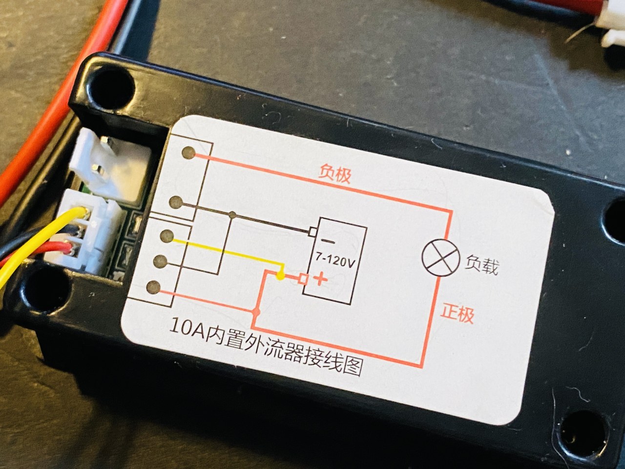
Configuration 1: Measuring a High-Voltage Battery (8V-120V) with No External Power
If the voltage of the battery or system you are measuring is between 8V and 120V, you can power the meter directly from the source. In this case, the meter's red wire is connected to the positive terminal of the battery, and the black wire to the negative. The yellow voltage-sense wire is also connected to the positive terminal. The load is connected in series with the meter's current path.
Configuration 2: Measuring a Low-Voltage Battery (0V-8V) with External Power
When measuring a system below 8V, the meter requires its own external power supply (8-120V DC) to operate. In this setup, the red and black wires are connected to the external power supply. The yellow voltage-sense wire is connected to the positive terminal of the battery you are measuring. The current path is the same: the positive of the battery goes to the meter's current input, and the load is connected to the current output.
Configuration 3: Using an External Shunt (for 50A, 100A, etc. versions)
The larger versions of this meter (50A, 100A) use an external shunt resistor. In this case, the shunt is placed in the negative return path of the circuit. The meter's voltage sense wires are connected across the shunt to measure the voltage drop, which is proportional to the current. The wiring is slightly different and clearly outlined in the included manual. (in video at 07:07)
It is critical to remember that the meter's internal power supply cannot handle more than 120V. If you are measuring a system above 120V, you must use an external power supply to power the meter itself. (in video at 09:32)
Testing and Calibration
The review involved testing the meter with a variable power supply and an electronic load. The voltage readings were found to be very accurate, matching the input voltage almost exactly. The current readings were also highly accurate, with only a slight offset of 20-30 milliamps at higher currents (e.g., showing 8.08A when 8.00A was drawn), which is a negligible error. (in video at 11:44)
The meter also has a "Wh" (Watt-hour) and "Ah" (Amp-hour) integration feature, which counts the total energy and charge consumed over time. The unit successfully retained these values even after being completely powered off and on again. (in video at 14:06)
If you find the readings are slightly off, you can calibrate the meter using the two small potentiometers on the back. The one closest to the shunt resistor adjusts the current reading, and the other adjusts the voltage. By carefully turning these tiny screws, you can fine-tune the display to match a known reference. (in video at 19:54)
Teardown and Internals
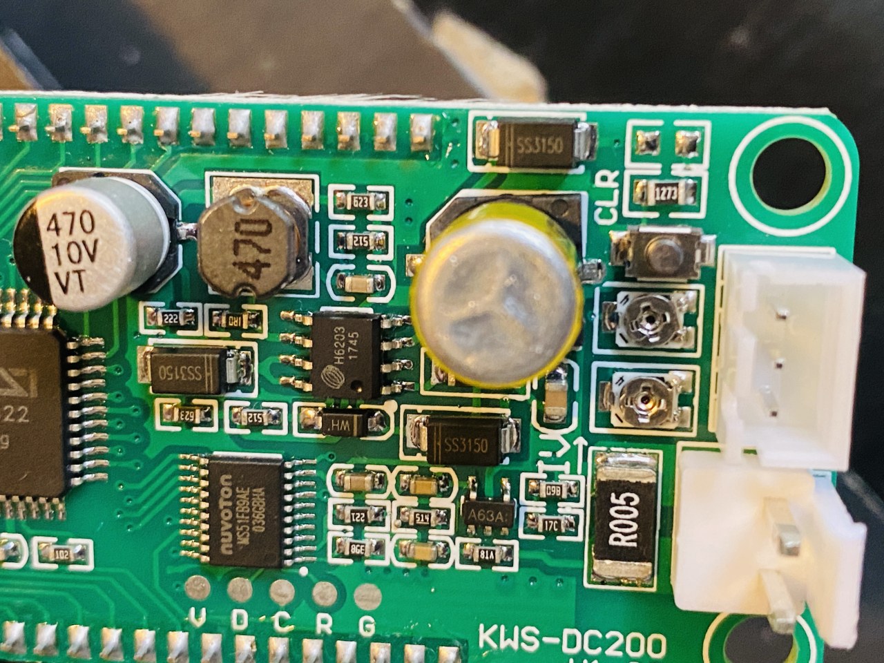
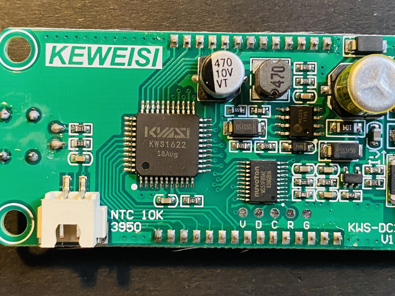
Opening the meter reveals a well-constructed, professional PCB. The main components are a Nuvoton MS51FB9AE microcontroller, which acts as the brain of the device, and an H6203 op-amp for signal conditioning. The internal shunt resistor is a substantial 0.05-ohm (5 milliohm) component designed to handle the full 10A of current. (in video at 16:36)
The review unit had a minor issue where the reset button on the back did not function as expected, despite a comment on a website suggesting it should work. This was likely a defect specific to this unit. Overall, the build quality is excellent, with clean soldering and professional assembly. (in video at 18:32)
Live Project / Demonstration
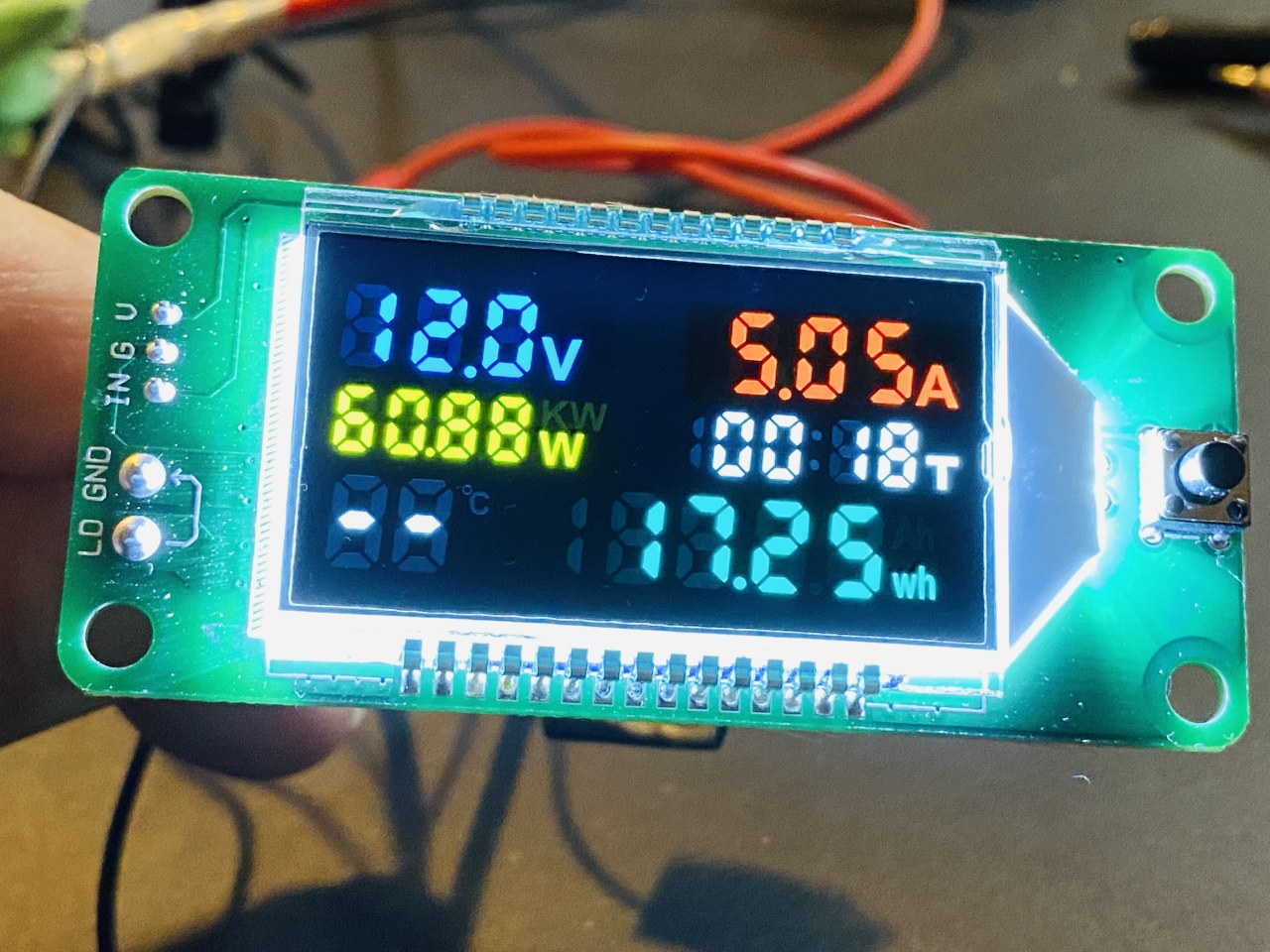
In a live demonstration, the meter was connected to a 12V power supply and an electronic load set to draw 5A. The meter accurately displayed 12.2V and 5A, confirming its real-world performance. The demonstration also highlighted the meter's ability to track energy consumption over time, showing the accumulated watt-hours and run time. This makes it a practical and reliable tool for any project requiring precise DC power monitoring. (in video at 20:36)
Chapters
- [00:00] Introduction and product overview
- [00:56] Unboxing and first impressions
- [03:35] Powering on and initial display check
- [06:27] Wiring guide and configurations
- [09:57] Testing voltage and current accuracy
- [13:56] Testing value retention after power-off
- [16:16] Teardown and internal component analysis
- [19:54] Calibration of voltage and current readings
- [22:03] Final thoughts and summary
Immagini

Cose di cui potresti avere bisogno
-
AmazonKWS-DC200 on Amazonamzn.to
-
eBayKWS-DC200 on eBayebay.us
-
AliExpressKWS-DC200 on AliExpresss.click.aliexpress.com
-
AliExpressKWS-DC200 on AliExpress-2s.click.aliexpress.com
-
BanggoodKWS-DC200 on Banggood USAbanggood.com
Risorse e riferimenti
Nessuna risorsa ancora.
File📁
Nessun file disponibile.