Calculating resistor values to measure any DC voltage using Arduino
The calculation in this article is shown in the video https://youtu.be/t8xwrVj2aFs to measure any DC voltage with Arduino.
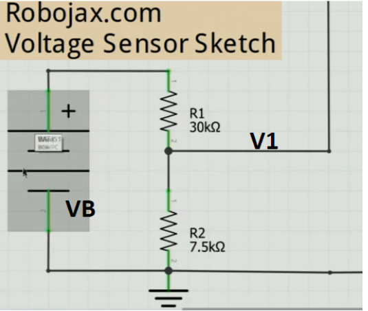
Voltage divider is used to calculate the the voltage for Arduino voltage sensor as shown in Fig. 1
In this figure we have got:
Battery voltage VB
Output voltage that goes to Arduino V1 input pin (i.e A0)
R1 is 30kΩ
R2 is 7.5kΩ
Arduino UNO accepts 5V at the input, therefore V1 is 5V. From this we can find the current I in both R1 and R2.
I=V/R and therefore I=5/7500=0.000666=666µA
Because R1 and R2 are in series, the current is the same for both. So IR2 is also 666µA. We can find the voltage across R1 as
VR1=666µ x 30000=20V.
Now we know the maximum voltage at V1 can be
VR1+VR2=5V+20V=25V.
Calculating Larger Voltage Values
We can add another resistor in series RX with this circuit as shown in Figure 2.
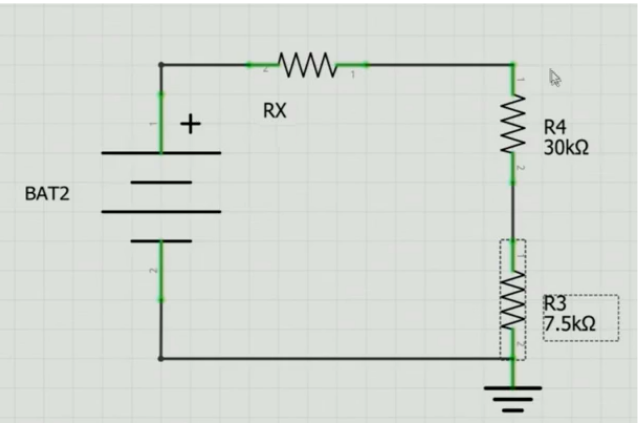
Figure 2. Series Resistor RX in circuit.
To find the value of RX for measuring BAT2 Voltage, we have:
RX=BAT2-25666uA
Now We have got the formula for RX, if for example BAT2 = 120V
Then
RX=120-25666uA=95666ua=142.5kΩ
So using a 142kΩ resistor as RX, we can measure up to a maximum of 120V.
Images
Resources & references
No resources yet.
Files📁
No files available.


![Arduino UNO R4 WiFi [ABX00087] - Renesas RA4M1 + ESP32-S3, Wi-Fi, Bluetooth, USB-C, CAN, 12-bit DAC, OP AMP, Qwiic Connector, 12x8 LED Matrix for Advanced IoT & Embedded Projects](https://m.media-amazon.com/images/I/416S910MpBL._SL75_.jpg)
![Arduino UNO R4 Minima [ABX00080]](https://m.media-amazon.com/images/I/41AF-Pi1ykL._SL75_.jpg)