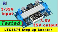
Test Review of LTC1871 Step Up 3-35V input to 3.5 to 35V output booster module
Introduction
This guide provides a detailed review and testing of the LTC1871-based step-up (boost) converter module. This device is a versatile and powerful solution for projects that require a higher voltage from a lower-voltage power source. It accepts a wide input range of 3 to 35V DC and can boost it to a stable, adjustable output of up to 35V DC. Its high-current capability, thanks to an external power MOSFET, makes it suitable for a variety of demanding applications.
Here are some practical uses for this type of booster module:
- Powering LED strips: Drive high-voltage LED strips (e.g., 12V or 24V) from a single 3.7V lithium-ion battery or a 5V USB power bank.
- Portable electronics: Create a custom power supply for portable speakers, displays, or other devices that need a voltage higher than your battery provides.
- Solar power systems: Step up the variable voltage from a small solar panel to a stable voltage for charging batteries or powering sensors.
- Bench power supply: Use it as a simple, adjustable bench supply for testing other circuits, providing up to 35V from a common 12V adapter.
- Automotive projects: Boost a car's 12V electrical system to 24V or 30V for specialized equipment.
This review will cover the module's hardware, its key components, and a series of load tests to determine its real-world performance and current limits. We will also explore its user interface, including the display and buttons.
Hardware Overview
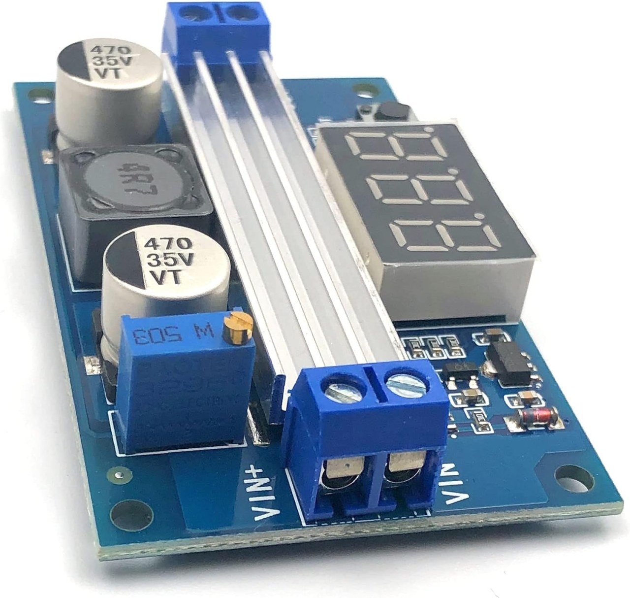
The module is compact and well-built, featuring a clear layout for easy integration into your projects. Let's take a closer look at its physical characteristics and main components.
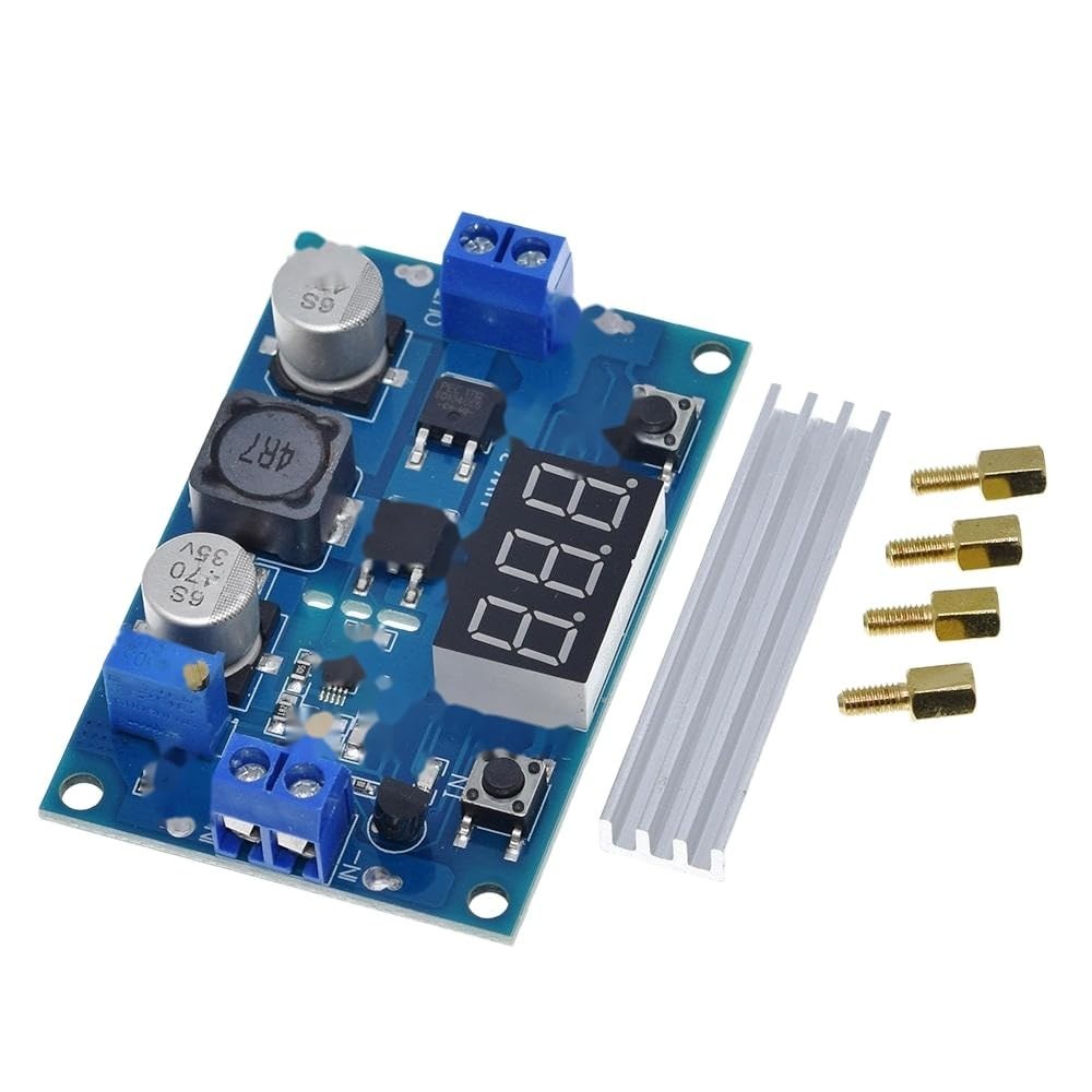
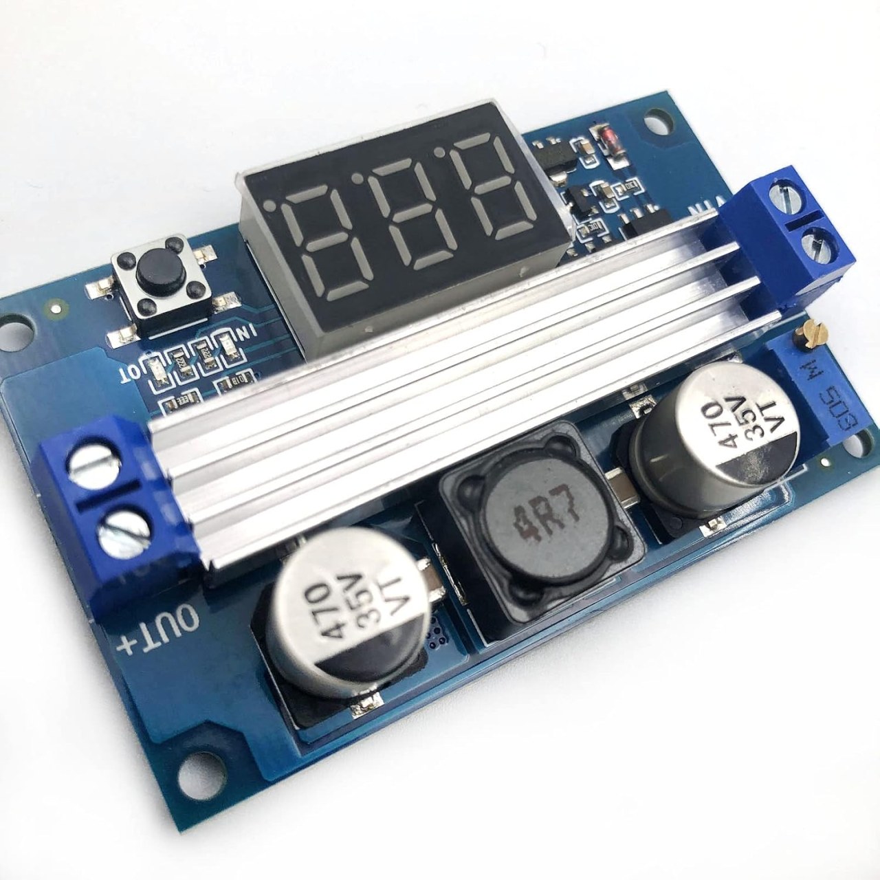
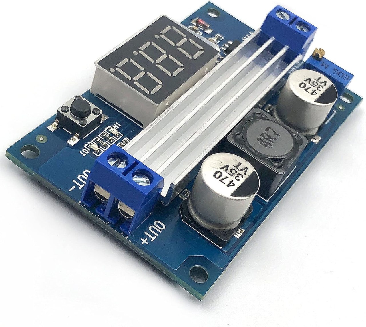
The board measures approximately 67.2mm in length and 43.8mm in width. The tallest components are the capacitors, which bring the total height to about 11.8mm. The module weighs around 20.7 grams, and this increases to 25 grams when the included heatsink is attached. It also has four mounting holes for screws and comes with standoffs for secure installation on a chassis or enclosure. (in video at 01:44)
Here is a breakdown of the key elements on the board:
- Input/Output Terminals: The board has clearly labeled screw terminals for the input (IN+) and output (OUT+) connections. The input accepts 3-35V, and the output can be adjusted up to 35V.
- Display and Buttons: A three-digit seven-segment display shows the current voltage. Two buttons are provided: one to toggle the display between showing the input or output voltage, and another to shut off the output entirely. (in video at 01:00)
- Voltage Adjustment: A small potentiometer on the board allows you to manually adjust the output voltage. Turning it clockwise increases the voltage. (in video at 05:36)
- LTC1871 Controller: This is the main boost converter IC. It operates over a wide input range of 2.5V to 36V and controls the switching of the power MOSFET. (in video at 02:42)
- Power MOSFET: This is a high-current N-channel MOSFET (model 4184) that handles the heavy lifting of switching current. It is rated for up to 40V and 50A, but the module is designed to deliver up to 6A. This is the component that requires the heatsink. (in video at 03:20)
- Schottky Diode: A dual Schottky diode is used for reverse polarity protection. If you accidentally connect the input power with the wrong polarity, this diode will short-circuit and protect the more sensitive components like the controller and MOSFET from damage. (in video at 03:53)
Wiring Guide
Wiring this module is straightforward. It has two sets of screw terminals for input and output. The polarity is clearly marked on the board.
To connect your power source and load:
- Connect the Input: Connect your DC power source (3-35V) to the terminal block labeled "IN+". Ensure you match the positive and negative wires correctly.
- Connect the Output: Connect your load (the device you want to power) to the terminal block labeled "OUT+". Again, match the polarity.
- Adjust the Voltage: Before connecting a sensitive load, it's a good practice to power the module, use the button to display the output voltage, and then adjust the potentiometer to your desired voltage.
The module includes reverse polarity protection via a Schottky diode, which will short-circuit if the input is connected incorrectly, preventing damage to the main components. This gives you time to correct the wiring without destroying the module. (in video at 04:03)
Live Project / Demonstration
The core of this review is the practical load testing to see how the module performs under real-world conditions. The tests were conducted using a 12V input, an electronic load, and a current clamp to measure input current. The heatsink was attached to the MOSFET for all tests, which is crucial for valid results. (in video at 05:11)
Test 1: 12V Input to 30V Output
This test aimed to see if the module could deliver its advertised 6A at a high boost ratio. The results were as follows:
- 6 Amps: The module failed. The output voltage dropped to 15V. (in video at 07:35)
- 5 Amps: The module failed again, with a significant voltage drop. (in video at 08:00)
- 4 Amps: The module failed as well. (in video at 08:34)
- 1 Amp: The module successfully supplied 1A at a stable 30V. The input current was measured at 3.6A, indicating a power draw of 43.2W on the input to deliver 30W at the output. (in video at 08:48)
Test 2: 12V Input to 24V Output
With a lower output voltage, the current capability improved, but still fell short of the 6A claim.
- 6 Amps: The module failed, with the output voltage dropping to 14V. (in video at 10:04)
- 5 Amps: The module failed, with a significant voltage drop. (in video at 10:23)
- 4 Amps: The module failed, dropping to 17V. (in video at 10:30)
- 3 Amps: The module failed. (in video at 10:43)
- 2 Amps: The module successfully supplied 2A at a stable 24V. The input current was measured at 5.3A. (in video at 10:47)
Test 3: 12V Input to 16V Output
This test used a lower boost ratio, which is less stressful on the converter.
- 4.5 Amps: The module successfully supplied 4.5A at a stable 16V. There was a slight voltage drop, so the current was reduced to 4.2A, at which point it was very stable. The input current was 6.5A. (in video at 11:09)
Test 4: 5V Input to 12V Output
This test demonstrates a common use case: boosting a 5V USB source to 12V.
- 2.4 Amps: The module successfully supplied 2.4A at a stable 12V. The input current was 6.2A. This setup was left running for over 10 minutes and worked perfectly. (in video at 12:20)
Conclusion from Testing
The tests show that while the module is advertised to handle up to 6A, this is only achievable at low boost ratios. The maximum current it can supply decreases as the difference between input and output voltage increases. The results were as follows:
- 12V to 30V: Max current is 1A.
- 12V to 24V: Max current is 2A.
- 12V to 16V: Max current is ~4.5A.
- 5V to 12V: Max current is 2.4A.
All these results are valid only with the heatsink attached. Without it, the performance will be significantly worse and the MOSFET may overheat. (in video at 13:07)
Chapters
- [00:06] Introduction to the LTC1871 Booster Module
- [00:49] Hardware Overview and Key Components
- [01:44] Physical Dimensions and Weight
- [02:42] Deep Dive into the LTC1871 Controller
- [03:20] The Power MOSFET and Schottky Diode
- [05:35] Testing the Voltage Adjustment and No-Load Operation
- [07:35] Load Test: 12V to 30V Output
- [10:04] Load Test: 12V to 24V Output
- [11:09] Load Test: 12V to 16V Output
- [12:20] Load Test: 5V to 12V Output
- [12:56] Performance Conclusion and Summary
图像
|||您可能需要的东西
-
全球速卖通Buy LTC1871 DC-DC Boost Converter Step Up Power Module from AliExpresss.click.aliexpress.com
资源与参考
尚无可用资源。
文件📁
数据手册 (pdf)
-
ST5333BTS DatasheetDatasheet for the ST5333BTS component. The document provides electrical characteristics, pinout, and application information for this part. Specific specifications are not detailed in the filename.
ST5333BTS_C324582_datasheet.pdf0.81 MB -
LTC1871 boost converter datasheetLTC1871 boost converter datasheet with specifications, pinout, and application information for DC-DC power supply design.
LTC1871_boost_converter_datasheet.pdf0.51 MB -
PANJIT SD1020CS SD1060CS schottky barrier rectifier diodePANJIT SD1020CS and SD1060CS Schottky barrier rectifier diode datasheet with electrical characteristics and specifications. Vrms 20V DC blockign max Vds 20V Max If 10A
PANJIT_SD1020CS_SD1060CS_schottky_barrier_rectifier.pdf1.14 MB -
Alpha & Omega D4184 AOB4184 40V N-channel mosfetThe AOB4184 uses advanced trench technology and design to provide excellent RDS(ON) with low gate charge. With the excellent thermal resistance of the D2PAK package, this device is well suited for high current load applications. VDS (V) =40V ID = 50 A (VGS = 10V) RDS(ON) < 10 mΩ (VGS = 10V) RDS(ON) < 13 mΩ (VGS = 4.5V)
Alpha_&_Omega_AOB4184_40V_N-channel_mosfet.pdf0.30 MB