IC Station Buck converter DC 9-35V to DC 5V 5A Test review
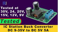
This guide provides a comprehensive test and review of the IC Station DC-DC buck converter module, which steps down a wide input voltage range of 9-35V DC to a fixed, regulated 5V output, capable of delivering up to 5A (25W). This type of converter is essential for projects where you need a stable 5V supply from a higher-voltage source, such as a battery bank or a vehicle's electrical system. This review will cover the module's design, performance under various input voltages and loads, and its thermal characteristics, giving you a clear picture of its capabilities and limitations.
This module is a practical solution for a variety of electronics projects. Here are some ideas on how you could use it:
- Powering a Raspberry Pi or Arduino from a 12V or 24V battery in a remote or mobile project.
- Creating a custom USB charging hub for your workbench, powered by a single high-voltage supply.
- Building a dedicated 5V power supply for LED strips, sensors, or other 5V logic circuits in a larger system.
- Stepping down a 24V industrial control panel voltage to power microcontrollers and sensors safely.
Hardware Overview
The IC Station DC-DC converter is a compact module designed for efficient voltage conversion. The video teardown reveals its key components and their roles in its operation (in video at 00:44).
- Input/Output Terminals: The module has three terminals: positive input (VIN+), a common ground (GND), and the positive 5V output (VOUT+).
- Reverse Polarity Protection: A Schottky diode (SS510) is placed in series with the positive input. This diode blocks current flow if the input polarity is reversed, protecting the rest of the circuit from damage. It's rated for 5A, which is sufficient as the input current will always be lower than the output current due to the voltage step-down.
- Inductor: A 6.1 µH inductor (ML33) is used for energy storage in the buck converter topology. It's rated to handle up to 12.5A, providing a good safety margin.
- PWM Controller IC: The core of the module is the Texas Instruments TPS40057, a wide-input (8-40V) synchronous buck controller. This chip manages the switching of the MOSFETs to regulate the output voltage.
- Power MOSFETs: Two Toshiba TPC8016H MOSFETs are used in the output stage. These are high-efficiency switches that handle the main current flow. They are rated for a drain current of 25A and a power dissipation of 45W each, meaning the two together are well-suited for the module's 5A rating.
Wiring Guide
Connecting the module is straightforward. The video demonstrates the connections clearly (in video at 04:19).
Connect your DC power source (9-35V) to the input terminals, and your 5V load to the output terminals.
- Input: Connect the positive wire from your power source to the "IN+" terminal and the negative wire to the "GND" terminal.
- Output: Connect the positive wire of your 5V load to the "OUT+" terminal and the negative wire to the "GND" terminal. The ground is common between the input and output.
Performance Testing
The review conducted a series of tests to evaluate the module's performance under different conditions. The results are summarized below.
Output Voltage Regulation (No Load)
The first test checked the output voltage stability across the entire input voltage range (in video at 04:39). The input voltage was varied from 30V down to 9V, and the output remained remarkably stable at 5.06V, which is a deviation of only about 1%.
It was also noted that the module would only produce a stable 5V output when the input was at least 9V, confirming the manufacturer's specification. Below this, the output became unstable.
Load Regulation and Ripple
The most critical tests involved applying a full 5A load to the output and measuring the voltage drop and ripple (in video at 07:02). The tests were conducted at various input voltages.
- At 30V Input: The voltage dropped by only 20mV to 5.04V, and the ripple was measured at 106mV.
- At 24V Input: After running for two minutes, the voltage drop was similar, and the ripple was around 104mV.
- At 15V Input: The voltage drop was about 60mV, and the ripple was 94mV with the load and 78mV without.
- At 12V Input: The output remained very stable.
- At 9V Input: The output voltage held at 5V with a 5A load. The ripple was measured at 66mV with the load and decreased to 54mV without it.
A key finding was that the ripple was lower when the input voltage was closer to the output voltage. The module consistently maintained a stable output voltage with minimal drop, even at the maximum rated current.
Thermal Performance
The module's temperature was monitored during the load tests (in video at 08:46). The main heat-generating components are the two MOSFETs and the inductor. The module gets noticeably hot, especially at higher input voltages.
At 30V input with a 5A load, the module became very hot to the touch. The reviewer noted that at 24V and above, the module requires adequate ventilation or a reduced current draw to ensure long-term reliability.
Conclusion
In conclusion, the IC Station DC-DC buck converter performs very well in its intended role (in video at 13:03). It delivers a clean, stable 5V output with a negligible voltage drop, even under a full 5A load. The ripple is within acceptable limits for most digital logic circuits. The primary consideration is thermal management; at higher input voltages and maximum load, the module can get quite hot, so you should ensure proper airflow in your enclosure or derate the output current if necessary.
Video Chapters
- [00:00] Introduction and product overview
- [00:44] Module hardware and component analysis
- [03:40] Manufacturer and product listing information
- [04:19] Setting up for testing and input voltage regulation test
- [07:02] Load test at 30V input
- [08:27] Load test and thermal check at 24V input
- [09:57] Load test at 15V input
- [11:13] Load test at 12V input
- [11:42] Load test at minimum 9V input
- [13:03] Conclusion and final thoughts
Risorse e riferimenti
Nessuna risorsa ancora.
File📁
Nessun file disponibile.