DC 0-100V 5A 10A 250W 999W LCD Digital Voltmeter Ammeter Voltage Current Power review - Robojax
Introduction
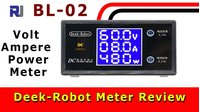
This guide provides a comprehensive review and testing walkthrough of the Deek-Robot DC 0-100V 10A digital voltmeter, ammeter, and wattmeter. This is a practical, all-in-one panel meter that allows you to monitor the electrical characteristics of a DC circuit in real-time. It's an essential tool for any electronics workbench, maker project, or DIY power supply setup.
The module's large, bright digital display shows three key metrics simultaneously: the voltage, the current, and the calculated power (in watts). This makes it incredibly convenient for troubleshooting, performance monitoring, and ensuring your circuits operate within safe parameters. The meter is available in different configurations (e.g., 5A/50V or 10A/100V) to suit a range of applications.
Here are some practical ways you can use this meter in your own projects:
- Bench Power Supply Monitoring: Add it to a variable power supply to always know the exact voltage and current being delivered to your circuit.
- Battery Discharge Testing: Monitor the voltage and current draw of a battery under load to estimate its state of charge and health.
- Solar Panel Output: Verify the real-time power output of a small solar panel to ensure it's performing as expected.
- Motor Current Draw: Check the current consumption of DC motors to identify if they are stalling or overworking.
- DIY Power Bank or Charger: Integrate it into a custom charger to display the charging voltage and current.
- Troubleshooting Circuits: Quickly identify if a circuit is drawing too much current, which can indicate a short circuit or component failure.
Hardware Overview
This meter is designed for simplicity and ease of use. It features a large, clear LCD with a bright backlight, making the readings easy to see even in dimly lit environments. A standout feature is the direct access to the calibration potentiometers on the front of the unit, allowing for quick and easy adjustment of both voltage and current readings without any disassembly.
The module is housed in a compact enclosure with a built-in clip, designed for secure mounting into a panel cutout. The physical dimensions are as follows:
- Module Length: 79.3 mm
- Module Width: 42.8 mm
- Panel Cutout Width: 39.1 mm
- Panel Cutout Length: 71.4 mm
- Module Depth (including connector): 41.8 mm
- Weight: 32.5 grams
When planning your panel, you must account for at least 30 mm of clearance behind the module to accommodate the connector and wiring.
Wiring Guide
Understanding the wiring is crucial for correct operation. This meter requires a separate power supply to operate its internal circuitry. This is a common design for such meters to ensure measurement accuracy is not affected by the circuit under test.
Power Supply (7-12V DC): The meter needs its own power source. Connect a 7V to 12V DC supply to the two thin wires (typically red and black). This powers the display and the measurement logic.
Voltage Measurement: To measure the voltage of your main circuit, you connect the third thin wire (often white or green) directly to the positive terminal of the power source you are measuring. This is a high-impedance connection that only senses the voltage and draws negligible current.
Current Measurement: This is done using the two thick wires. The current must flow through the meter. The circuit must be broken, and the meter is inserted in series. The positive terminal of your power source connects to one thick wire. The current then flows through an internal shunt resistor and exits from the other thick wire, which then connects to your load's positive terminal. The negative side of the circuit is connected directly from the power source to the load.
Here is a simple way to visualize the current path:
- Power Source (+) → Meter Thick Wire (In)
- Meter Thick Wire (Out) → Load (+)
- Load (-) → Power Source (-)
The voltage drop across the meter's shunt resistor is minimal (around 48mV at 10A), so it has a negligible impact on your circuit's performance.
Please refer to the wiring diagram below for a visual representation of these connections.
Live Demonstration and Testing
In the video, the meter is put through a series of tests to verify its accuracy and functionality.
Power Measurement: The meter was connected to an electronic load to test its power calculation. With a constant current draw of 2.36A, the power was correctly displayed as 34.2W. When the voltage was increased, the power reading increased proportionally, confirming the P = V × I calculation. The meter accurately displayed power readings up to its maximum rating of 1000W.
Current Measurement: The meter was tested with various current draws. It was confirmed to be very accurate at its maximum rated current of 10A. The test showed that the meter will not display values beyond its 10A limit, even if more current is forced through it. At 15A, the display remained at 11A, indicating the internal sensor is capped at its design limit.
Voltage Calibration: The video demonstrates how to calibrate the voltage reading. By connecting a known, accurate voltage source (21.4V in the test) to the meter and adjusting the voltage potentiometer, the display can be fine-tuned to match the reference reading exactly.
Shunt Resistor Voltage Drop: A key measurement was the voltage drop across the internal shunt resistor. With 10A of current flowing, the drop was measured at a very low 48 millivolts (mV). This is excellent and ensures minimal power loss in the measurement path. This value can be used to calculate the shunt's resistance using Ohm's Law (R = V/I), which yields 0.048V / 10A = 0.0048Ω, or 4.8 milliohms.
Conclusion
The Deek-Robot DC 0-100V 10A power meter is a highly recommended, accurate, and easy-to-use device. Its large, bright display and simple wiring make it a great addition to any electronics project. The direct-access calibration potentiometers are a significant advantage, making it simple to ensure precise readings. Whether you are a hobbyist or a professional, this meter is a reliable and valuable tool for monitoring DC power.
Video Chapters
- [00:00] Introduction and Product Overview
- [00:23] Module Features and Specifications
- [01:53] Display and Physical Dimensions
- [02:56] Wiring Explained
- [03:01] How to Measure Current
- [04:33] Detailed Wiring Diagram and Connections
- [08:00] Current and Power Consumption Demonstration
- [10:35] Calibrating Voltage
- [11:27] Measuring Shunt Resistor Voltage
- [12:06] Conclusion and Final Thoughts
Resources & references
No resources yet.
Files📁
No files available.