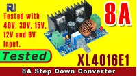
Review of XL4016E1 DC-DC Step Down Power Supply Module 4V-40V to 1.25-36V 8A
Introduction
In this project review, we take an in-depth look at the XL4016E1 DC-DC Step Down Power Supply Module, a versatile and powerful buck converter capable of handling up to 8 amperes of current. This module is an essential component for any electronics workbench, allowing you to efficiently step down a higher DC voltage to a lower, stable one. Whether you are powering a microcontroller, LED strips, or a custom robotics project, this module provides a reliable and adjustable power solution. Its high efficiency and wide input voltage range make it ideal for a variety of applications.
Here are a few practical examples of what you can build or improve with this module:
- Powering an LED strip: Step down a 12V or 24V supply to the exact voltage required for high-power LED lighting, ensuring consistent brightness.
- Bench power supply: Create a variable bench power supply for your electronics lab, allowing you to test circuits at different voltages (1.25V to 36V).
- Battery-powered projects: Regulate the voltage from a battery pack (e.g., 4S LiPo) down to a stable 5V or 3.3V for your microcontrollers and sensors.
- 3D printer or CNC upgrades: Provide a clean, dedicated power rail for auxiliary components like fans, lights, or a Raspberry Pi.
- Automotive projects: Safely power sensitive electronics in a car by stepping down the 12V battery voltage to a stable 5V or 9V.
Hardware Overview
The XL4016E1 module is a compact and well-built switching regulator. The core of the module is the XL4016E1 IC from XL Semiconductor, a high-efficiency buck converter. The module features a large inductor for energy storage, input and output capacitors for filtering, and a Schottky diode for rectification. It also includes a potentiometer for adjusting the output voltage and an on/off switch for the output, which is a handy feature for testing and power management.
The module measures approximately 65.1mm x 42.5mm and weighs 48.7 grams. It has four mounting holes and can be fitted with standoffs, making it easy to install in enclosures. The input and output terminals are clearly marked, and the module includes a power LED that indicates when the output is active.
Hardware/Components
For this review and testing, the following components were used:
- XL4016E1 DC-DC Step Down Power Supply Module
- Variable DC power supply (for input voltage)
- Electronic load (DL3031) to simulate different current draws
- Digital multimeters (for voltage and current measurements)
- Power meter (to measure input voltage, current, and power)
- Thermal camera (to monitor component temperatures)
Wiring Guide
The wiring for this module is straightforward. As the presenter explains in the video, the input voltage is connected to the "IN" terminals, and the load is connected to the "OUT" terminals. A power meter is placed in series with the input to measure input voltage and current, while the output is connected to an electronic load to simulate various current draws. The module's output voltage is adjusted using the onboard potentiometer.
Code Explanation
This project is a hardware review, and as such, no code is required or provided. The XL4016E1 module is a purely analog component, configured entirely through its onboard potentiometer. To set the desired output voltage, you simply connect the input power, attach a load, and turn the potentiometer until the output voltage matches your target. It is recommended to check the output with a multimeter while making adjustments.
Live Project/Demonstration
The testing process involved a series of rigorous tests to evaluate the module's performance under various input and output conditions. The presenter systematically tested the module's ability to maintain a stable output voltage while drawing different amounts of current. Key tests included:
- Minimum Output Voltage: With a 30V input, the module was able to adjust its output down to a minimum of 1.268V.
- Maximum Output Voltage: With a 40V input, the maximum stable output was 36V.
- Voltage Regulation: The module was tested to see how well it maintained a set output voltage (e.g., 5V, 15V, 3.3V) as the input voltage was lowered. It was found that a minimum input voltage of about 5.5V is required to maintain a stable 5V output.
- Current Handling: The module was subjected to various current loads up to 8A. In many configurations, it handled 8A with a minimal voltage drop. However, in some cases, such as a 12V output from a 30V input, the module struggled to maintain stability at higher currents, exhibiting a significant voltage drop. The presenter noted that at 5A, the module performed excellently in most scenarios.
- Efficiency: The efficiency was calculated by dividing the output power by the input power. The tests showed an efficiency of around 76% to 81% in various configurations, which is typical for a switching regulator under load.
- Thermal Performance: A thermal camera was used to monitor the temperature of the regulator IC and the Schottky diode. During high-load tests, the regulator IC reached temperatures of up to 100°C, which is within the operating junction temperature range but indicates that adequate cooling may be necessary for sustained high-power use.
The demonstration concluded that the XL4016E1 is a stable and well-designed module. While it can handle 8A in many cases, the presenter recommends using it with a 5A load for optimal stability and performance, as some voltage configurations showed significant drops at higher currents.
Chapters
- [00:00] Introduction and Project Overview
- [00:38] Module Overview and Purchase Options
- [01:52] Module Components and Features
- [03:16] Datasheet Review and Specifications
- [05:39] Understanding Power and Efficiency
- [06:59] Test Setup and Wiring Explanation
- [08:20] Testing Minimum and Maximum Output Voltage
- [09:31] Testing Voltage Regulation with Variable Input
- [11:53] Testing Output at 24V with 30V Input
- [12:43] Testing Output at 15V with 30V Input
- [13:56] Testing Output at 12V with 30V Input
- [15:53] Testing Output at 5V with 30V Input
- [16:29] Testing Output at 3.3V with 30V Input
- [17:27] Testing Output at 36V with 40V Input
- [18:34] Testing Output at 24V with 40V Input
- [20:54] Testing Output at 15V with 40V Input
- [23:00] Testing Output at 12V with 40V Input
- [23:47] Testing Output at 5V with 40V Input
- [24:43] Testing Output at 3.3V with 40V Input
- [25:36] Testing Output at 12V with 15V Input
- [27:14] Testing Output at 3.3V with 15V Input
- [27:49] Testing Output at 5V with 12V Input
- [28:07] Testing Output at 3.3V with 12V Input
- [28:55] Testing Output at 5V with 9V Input
- [29:34] Conclusion and Final Thoughts
Ресурсы и ссылки
Ресурсов пока нет.
Файлы📁
Нет доступных файлов.