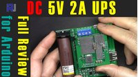
Review of Roottronics LUPS-05 DC 5V 2A UPS for Arduino and Raspberry Pi using 18650 Lithium battery
This guide reviews the Roottronics LUPS-05, a low-voltage uninterruptible power supply (UPS) designed to keep your 5V projects running seamlessly through power outages. This compact module ensures your Arduino, Raspberry Pi, or other sensitive electronics stay operational without interruption, making it ideal for critical applications where data loss or system downtime is not an option. It intelligently switches to battery power the instant your main supply fails, then recharges the battery automatically when power is restored.
Here are a few practical applications for this UPS module:
- Home Automation Hubs: Keep a central Raspberry Pi or Home Assistant server online during brief power flickers.
- Remote Sensor Stations: Ensure data loggers and environmental sensors continue to record data even when the main power grid is unstable.
- Security Systems: Provide backup power to an Arduino-based alarm system or IP camera, preventing gaps in surveillance.
- Network Equipment: Power a router or network switch to maintain an internet connection for laptops and phones during an outage.
- 3D Printers: Prevent a print job from being ruined by a power cut, allowing the printer to either finish or pause gracefully.
Hardware Overview
The LUPS-05 is a versatile power management board. It accepts 5V input from either a micro USB port or a dedicated two-pin terminal. This input power serves two purposes: it powers your device at the output, and it charges the onboard 18650 lithium battery. When the input power is lost, the module instantly switches to boost converter mode, stepping up the battery's 3.7V to a steady 5V output. This model is rated for a continuous output of up to 2A. A 12V version is also available, which uses a barrel jack for output instead of a USB-A port.
Hardware Components
The module is built around several key components that handle charging, power conversion, and protection. Here is a breakdown of the main parts:
- TP4056 (Battery Charger): A standalone linear lithium-ion charger that manages the charging of the 18650 battery with a default charge current of around 230mA.
- LM393 (Dual Comparator): Used for monitoring and protection functions, such as under-voltage and over-current detection.
- 8205A (Dual MOSFET): Acts as a protection switch, capable of handling high currents and disconnecting the battery in fault conditions.
- Boost Converter: A circuit (including an inductor and capacitors) that steps up the 3.3-4.2V from the battery to a stable 5V output.
- Power Switch: A physical switch to turn the module's output on or off.
- USB-A Output Port: The standard USB port where you connect your device's power cable.
- Micro USB Input: The primary port for supplying 5V input power.
- 2-Pin Input Terminal: An alternative way to connect an external 5V power source.
- LBO Pin: A "Low Battery Output" pin that can be used to signal a microcontroller when the battery is critically low.
Wiring Guide
Wiring the LUPS-05 is straightforward, but it is critical to follow the input power rules to avoid damaging the module. The output is as simple as plugging in a USB cable.
Here is how to connect everything:
- Power Input: You have two options for supplying 5V power. Choose only one:
- Connect a standard micro USB cable to the module's micro USB port.
- Connect a regulated 5V supply to the two-pin terminal, observing correct polarity (positive and negative).
- Battery: Insert a single 18650 lithium-ion battery into the holder. The module will handle charging and discharging automatically.
- Power Output: Connect a USB cable from the module's USB-A port to your device (e.g., Arduino or Raspberry Pi).
Warning: Never supply power from both the micro USB port and the terminal pins simultaneously. This can damage the board.
Code Explanation
No code is required to use this UPS module as a standalone power supply. It functions entirely in hardware. However, the LBO (Low Battery Output) pin is a valuable feature for projects that need to react to a low battery state. This pin is an open-collector output that will go LOW when the battery is nearly drained, giving you a warning before the module shuts down completely.
To use this feature, you would connect the LBO pin to a digital input pin on your microcontroller (e.g., an Arduino). You would also need a pull-up resistor (typically 10kΩ) from that pin to 5V. Your code would then monitor this pin. When it reads LOW, your program can execute a safe shutdown sequence, such as saving data to an SD card or sending a notification, before power is lost.
Live Project Demonstration
In the video, the reviewer performs a series of tests to verify the module's performance. He first demonstrates that the output voltage remains a steady 5.32V when powered by the input and when switching to battery power, showing there is no interruption during the transition. The review then moves on to efficiency testing using an electronic load, measuring the efficiency at various current draws from 100mA up to the maximum 2A. The results show an efficiency range of 71% to 83%, with the highest efficiency observed at lower currents (400-500mA).
A thermal imaging test was also conducted while the module was delivering 2A. The hottest spot on the board reached only 44°C, indicating that the module runs very cool, which is excellent for reliability and longevity. The reviewer also measures the idle current draw of the module, which is a low 37mA, making it suitable for battery-powered applications.
Chapters
- [00:00] Introduction and Product Overview
- [01:29] Example Use Case with Arduino
- [03:14] Pricing and Product Options on Website
- [04:32] Unboxing and Physical Dimensions
- [05:16] Key Features and Specifications
- [08:05] Important Electrical Specifications
- [10:34] Component Analysis and Datasheets
- [12:59] Testing: Input, Output, and Battery Voltages
- [14:41] Testing: Battery Charging and Power Interruption
- [18:27] Efficiency Testing with Electronic Load (1A to 2A)
- [21:32] Thermal Imaging Test at 2A Load
- [25:01] Detailed Efficiency Measurements (100mA to 2A)
- [32:44] Low Battery Output (LBO) Pin Feature
- [34:55] Conclusion and Final Recommendation
Ressourcen & Referenzen
Noch keine Ressourcen vorhanden.
Dateien📁
Keine Dateien verfügbar.