Fix the 150W 10A Electronic Load not reading current
Introduction
This project is a practical guide to diagnosing and repairing a common failure in a 150W 10A electronic load: the device powers on but refuses to draw any current. This is a frustrating issue, as the load appears dead even with a proper voltage source connected. The root cause is often a blown input fuse, which can occur from a simple polarity reversal or a transient overload. This guide will walk you through the troubleshooting process, from identifying the symptoms to opening the unit, testing the components, and performing a temporary fix to get your device back in working order.
This repair is useful for anyone who relies on electronic loads for testing power supplies, batteries, or solar panels. Understanding this repair process can save you the cost of a new unit and give you confidence in basic electronics troubleshooting. Here are a few practical scenarios where this skill comes in handy:
- Testing Power Supplies: Verifying that a bench power supply can deliver its rated current without sagging or shutting down.
- Battery Discharge Testing: Checking the actual capacity of rechargeable batteries by drawing a constant current and measuring the discharge time.
- Solar Panel Characterization: Loading a solar panel to find its maximum power point and ensure it's performing to spec.
- LED Driver Testing: Ensuring constant-current LED drivers are delivering the correct current to avoid premature LED failure.
Hardware / Components
Before you begin, it is helpful to have the following tools and components on hand. Most of these are standard items for any electronics workbench.
- The 150W 10A Electronic Load unit itself.
- A small Phillips head screwdriver to open the enclosure.
- A digital multimeter with a continuity tester function.
- A bench power supply or a battery to use as a test source.
- A replacement fuse (e.g., 10A, 125V fast-acting fuse).
- A short piece of wire (for the temporary bypass fix).
Wiring Guide
This repair does not involve a complex wiring guide, as it focuses on internal component replacement. However, understanding the basic internal layout is crucial. The video shows a simple series path from the input terminals through a protective fuse and a reverse-polarity protection diode before reaching the main MOSFET.
A wiring diagram is not provided in the video, but the internal connections are straightforward:
- Input (+) connects to the fuse.
- The fuse connects to the load's main circuit (the MOSFET).
- A protection diode is placed in parallel with the input to shunt reverse voltage and blow the fuse, protecting the more expensive MOSFET.
In this case, the reverse polarity caused the protection diode to conduct, which in turn blew the fuse. The repair is simply replacing the blown fuse.
Troubleshooting & Repair
The video demonstrates a clear, methodical approach to diagnosing the issue. The first step is to observe the symptoms. When a 12V source is connected and the current draw is set, the load does nothing. However, disconnecting the voltage source triggers an "overload" beep. This is a key clue. The beep indicates the control circuitry is working, but the main power path is broken.
Following this logic, the next step is to open the unit to inspect the power path components. The video highlights two critical components: the fuse and a protective diode. Using a multimeter in continuity mode, the presenter quickly identifies the fuse as the culprit, as it shows an open circuit (no continuity).
Since a replacement fuse was not immediately available, a temporary workaround was implemented: a piece of wire was soldered across the fuse terminals. This is a valid troubleshooting technique to confirm the diagnosis, but it is crucial to remember that this bypass removes the over-current protection. The device should not be used for extended periods in this state, as a short circuit could damage the main MOSFET. The video emphasizes the need to replace the bypass with a proper fuse as soon as possible.
Code Explanation
No code is provided or required for this project, as it is a purely hardware-based repair.
Live Project / Demonstration
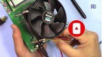
After the temporary fix, the presenter demonstrates the repair by connecting the electronic load to a 12V power supply. The load is now able to draw current as expected. The demonstration shows the load successfully drawing 7 amperes, and then being pushed to its maximum of 10 amperes. To verify the unit is functioning correctly under stress, the temperature sensor is checked, showing a reading of 57 degrees Celsius, which confirms the MOSFET is actively dissipating power and the cooling system is working. This successful test confirms that the fuse was indeed the only faulty component.
Chapters
- [00:05] Identifying the Problem: No Current Draw
- [00:45] Opening the Unit and Initial Inspection
- [01:08] Testing the Fuse and Diode
- [01:23] Diagnosing the Blown Fuse
- [01:39] Temporary Fix with a Wire Bypass
- [02:05] Reassembling and Powering On
- [02:26] Testing with a 12V Power Supply
- [02:54] Testing at Maximum Load (10A)
- [03:00] Verifying Temperature Sensor
- [03:16] Conclusion and Final Thoughts
منابع و مراجع
هنوز هیچ منبعی موجود نیست.
فایلها📁
هیچ فایلی موجود نیست.