Este tutorial es parte de: Makerfabs MaTouch AI ESP32S3 2.8" Camera
The latest MaTouch AI board integrate I2S voice input/I2S speaker/ 3 million camera OV3660/ 320*240 resolution display, with ESP32S3 strong processor& Wifi ability, to make this board a good tool/platform for AI development with ESP32.
Makerfabs MaTouch ESP32-S3 2.8" Camera and Touchscreen: 3MP Photos to SD Card
Live viewfinder, 3 megapixel photos, saved to SD with a real timestamp
A working camera app: a live viewfinder at about 25 frames per second, three touch buttons, and photos saved to the microSD card stamped with the correct date and time from the board’s battery-backed clock.
 Camera and Touchscreen running on the MaTouch AI ESP32-S3 board
The three buttons
SNAP - instant photo at the viewfinder resolution. Fast and always works.
3 MP - a real 2048×1536 photo. The screen goes dark for about two seconds; that is the camera driver restarting, and it is explained below.
FLIP - mirrors the image for when you point the lens away from yourself.
Why the screen goes dark for the 3 MP shot
A camera’s pixel format is fixed when the driver starts. You can change the resolution on the fly, but you cannot switch from RGB565 (what the screen needs) to JPEG (what the file needs) without restarting the driver. So the high-resolution path calls esp_camera_deinit(), restarts in JPEG mode at full resolution, takes the shot, then restores the viewfinder. The pause is honest, not a bug.
Timestamps without the internet
Photos are saved as /IMG_260730_143052.jpg - year, month, day, hour, minute, second. That comes from the PCF8563T real-time clock, which is kept running by the battery, so the time survives being unplugged. If the clock has lost power, the sketch seeds it from the moment the sketch was compiled.
A correction to the manufacturer’s example
The vendor’s own camera example defines the SD card on pins 2, 42 and 41. Those pin numbers are copied from a different board - on this one they are the microphone pins. The SD card is actually on the display’s SPI bus with its own chip select on IO47, which is what the code here uses. This matters if you ever want the camera and the microphones working in the same sketch.
Sharing one SPI bus
The display and the SD card sit on the same three wires, so both must go through the same SPI driver. This sketch uses Arduino_HWSPI with the standard SPI object for exactly that reason. Using a different driver for each is the classic cause of a display that freezes the moment the SD card is mounted.
About the MaTouch AI ESP32-S3 2.8" board
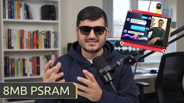
Every project on this page runs on the MaTouch AI ESP32-S3 2.8" TFT ST7789V from Makerfabs. It is an all-in-one board: a colour touchscreen, a 3 megapixel camera, two microphones and a real speaker amplifier, all driven by an ESP32-S3 with 8 MB of PSRAM. That combination is what makes these AI projects possible on a single board with nothing else attached.
The 8 MB of PSRAM matters more than any other number here. It is what lets the board hold a camera frame, a few seconds of recorded audio, or a base64-encoded photo in memory at the same time - none of which fits in the ESP32’s normal RAM.
Manufacturer documentation: Makerfabs wiki page.
Key specifications
Processor: ESP32-S3, dual core 240 MHz, WiFi 2.4 GHz + Bluetooth 5.0
Memory: 16 MB flash, 8 MB PSRAM (required by nearly every project here)
Display: 2.8" IPS, 320×240, ST7789V driver, SPI
Touch: GT911 capacitive, tracks 5 fingers at once
Camera: OV3660, 3 megapixel, up to 2048×1536
Microphones: two INMP441 I2S digital mics (a genuine stereo pair)
Speaker: MAX98357A class-D amplifier, 3.2 W into 4 Ω
Storage: microSD card slot (SPI mode)
Power: USB-C, JST battery connector, TP4056 charger, power switch
Also on board: WS2812B RGB LED, PCF8563T battery-backed real-time clock, and a MAX17048 battery fuel gauge that is not listed in the official specifications
The two USB-C ports are not the same. The board’s speaker shares its signal pins (IO19 and IO20) with the native USB port, because those pins are the ESP32-S3’s hardwired USB data lines. Always upload and power through the CH340K USB-C port (the one beside the RESET button), and set USB CDC On Boot to Disabled. Use the wrong port and audio will misbehave or uploads will fail.
Arduino IDE settings
These settings matter. Most problems people report with this board are one of these being wrong, and they reset when you change the core version, so check them again after any change.
Setting | Value |
|---|---|
Board | ESP32S3 Dev Module |
ESP32 core version | 2.0.17 |
PSRAM | OPI PSRAM |
Flash Size | 16MB (128Mb) |
Partition Scheme | 16M Flash (3MB APP/9.9MB FATFS) |
USB CDC On Boot | Disabled |
Upload Speed | 921600 |
Erase All Flash Before Upload | Disabled |
Port | the CH340K USB-C port |
Use ESP32 core 2.0.17, not 3.x. Espressif removed the on-device face detection models in core 3, so the face projects will not compile there. Pinning 2.0.17 keeps every project on this page working with one configuration. In Boards Manager, the version dropdown lets you switch back and forth whenever you like.
Use GFX Library for Arduino version 1.5.6, not 1.6.x. The 1.6 releases are built for ESP32 core 3 and can hang at start-up on core 2.0.17. If your screen stays black after uploading, this is the first thing to check.
Required libraries
Install these through Tools → Manage Libraries in the Arduino IDE. Version numbers matter - please use the ones listed.
Library | Version | Author |
|---|---|---|
GFX Library for Arduino | 1.5.6 | moononournation |
bb_captouch | 1.3.1 | Larry Bank |
Troubleshooting
Symptom | Cause and fix |
|---|---|
Screen stays black | Wrong GFX library version (use 1.5.6) or wrong board settings. |
|
|
Nothing uploads / no COM port | Wrong USB-C port, or the CH340 driver is not installed. |
Camera fails and never recovers | The camera’s reset line is tied to the board RESET button, so software cannot restart it. Press RESET. If it still fails, reseat the camera ribbon cable. |
Download the code
The complete Arduino sketch for this project, together with pins.h and everything else it needs, is free to download.
Unzip it, open the .ino file in the Arduino IDE, check the settings above, and upload through the CH340K USB-C port.
Where to buy this board
These are affiliate links. They cost you nothing extra and they help support the free code and tutorials on this site - thank you.
Este tutorial es parte de: Makerfabs MaTouch AI ESP32S3 2.8" Camera
- How to Use Makerfabs ESP32 3.5" TFT Capacitive Touch with Camera
- Makerfabs MaTouch ESP32-S3 2.8" camera Offline Face Detection on ESP32-S3 - No Internet, No API Key
- Makerfabs MaTouch ESP32-S3 2.8" camera Build an AI Voice Assistant on ESP32-S3 (Azure + DeepSeek)
- Makerfabs MaTouch ESP32-S3 2.8" camera ESP32-S3 AI Vision: Point the Camera and Ask What It Sees
/*
 * ===========================================================================
 *  02_Camera_Touch  —  MaTouch AI ESP32-S3 2.8" TFT ST7789V
 * ===========================================================================
 *
 *  ---------------------------------------------------------------------------
 *  VIDEO AND WRITTEN INSTRUCTIONS
 *
 *      Watch the video : https://youtu.be/Px3FT47RV2M
 *      Full article    : https://robojax.com/RTJ849
 *                        ("Camera and Touch" - wiring, settings, screenshots
 *                         and answers to the common problems)
 *
 *  Watching the video first will save you time - it shows the Arduino IDE
 *  settings and the library versions being set up step by step.
 *  ---------------------------------------------------------------------------
 *
 *  Live camera viewfinder with a touch interface, saving real photos to the
 *  microSD card, each one stamped with the true date and time from the board's
 *  battery-backed RTC.
 *
 *  Three buttons down the right hand side:
 *
 *      SNAP    quick save. Converts the frame already on screen to JPEG.
 *              Instant, 240x240, always works.
 *
 *      3 MP    the real thing. Tears the camera down, brings it back up at
 *              2048x1536 JPEG, takes the shot, and restores the viewfinder.
 *              Takes a couple of seconds. This is the OV3660's full
 *              3 megapixels, not an upscale.
 *
 *      MIRROR  flips the image, for when you turn the board around to point
 *              the lens at someone else.
 *
 *  Photos land on the SD card as  /IMG_260729_143052.jpg
 *
 *  No WiFi, no API keys, no internet.
 *
 *  ---------------------------------------------------------------------------
 *  WHY THE 3 MP BUTTON HAS TO WORK SO HARD
 *  A camera's pixel format is fixed when the driver starts. You can change the
 *  resolution on the fly, but you cannot switch RGB565 (what the screen wants)
 *  to JPEG (what the SD card wants) without restarting the driver. So the
 *  hi-res path deinitialises and reinitialises. That is normal, and it is why
 *  the screen goes black for a moment.
 *
 *  ---------------------------------------------------------------------------
 *  BOARD SETTINGS - see pins.h. In short: ESP32S3 Dev Module, core 2.0.17,
 *  OPI PSRAM, 16MB flash, 16M partition scheme, upload via the CH340K port.
 *
 *  LIBRARIES
 *      GFX Library for Arduino   v1.5.6
 *      bb_captouch               v1.3.1
 *
 *  ---------------------------------------------------------------------------
 *  FUNCTIONS IN THIS SKETCH
 *      rtcRead() / rtcWrite(...)   read/set the PCF8563 battery-backed clock
 *      rtcSeedFromBuildTime()      set the clock from compile time if it lost power
 *      getTouch(&x,&y)       read the touch panel, mapped to screen coordinates
 *      inBox(...)            hit-test a touch against a button rectangle
 *      camStart(...)         start the camera in a given format/size
 *      camStartPreview()     start the 240x240 RGB565 live-view camera
 *      makeFilename(...)     /IMG_YYMMDD_HHMMSS.jpg from the RTC time
 *      writeToSD(...)        save a buffer to the SD card
 *      snapQuick()           SNAP button: re-encode the preview frame to JPEG
 *      snapHiRes()           3MP button: restart camera in JPEG mode, full res
 *      drawButton(...) / drawButtons() / drawStatus()   the touch UI
 *      setup() / loop()      boot / viewfinder + edge-detected button taps
 *
 *  Robojax.com
 * ===========================================================================
 */

#include <Arduino_GFX_Library.h>
#include <bb_captouch.h>
#include <Wire.h>
#include <SPI.h>
#include <SD.h>
#include "esp_camera.h"
#include "img_converters.h"      // frame2jpg()
#include "pins.h"

/* The TFT and SD share pins 13/12/48, so both must go through the SAME SPI
 * peripheral: Arduino_HWSPI wraps the standard SPI object the SD library
 * uses. (Arduino_ESP32SPI would grab a different peripheral, and the display
 * goes dark the moment the SD card claims the pins.) */
Arduino_HWSPI *bus = new Arduino_HWSPI(
    TFT_DC, TFT_CS, TFT_SCLK, TFT_MOSI, TFT_MISO, &SPI, true /* shared bus */);
Arduino_GFX *gfx = new Arduino_ST7789(bus, TFT_RES, 1, true);

BBCapTouch bbct;

/* --- layout: 240x240 viewfinder on the left, 80px button column on the right */
#define VIEW_W    240
#define BTN_X     242
#define BTN_W      78

#define BTN_SNAP_Y    2
#define BTN_HIRES_Y  62
#define BTN_MIRROR_Y 122
#define BTN_H        56
#define STATUS_Y    186

bool ok_sd     = false;
bool ok_rtc    = false;
bool mirrored  = true;      // the lens is upside down relative to the screen
int  shot_count = 0;
char status[48] = "ready";

/* --- the RTC time structure ------------------------------------------------
 * Defined up here, before any function, with explicit prototypes below.
 * WHY: the Arduino IDE auto-generates function prototypes and can insert them
 * ABOVE this struct - a function returning RtcTime then fails to compile with
 * "RtcTime does not name a type". Writing the prototypes ourselves stops the
 * IDE generating its own, so the order stays correct.
 * ------------------------------------------------------------------------- */
struct RtcTime {
  int year, mon, day, hour, min, sec;
  bool valid;
};

// explicit prototypes - do not remove (see comment above)
RtcTime rtcRead();
void    rtcWrite(int year, int mon, int day, int hour, int min, int sec);
void    rtcSeedFromBuildTime();
bool    getTouch(uint16_t *x, uint16_t *y);
bool    camStart(pixformat_t fmt, framesize_t size, int fb_count, int quality);
bool    camStartPreview();
void    makeFilename(char *out, size_t n);
bool    writeToSD(const char *path, const uint8_t *data, size_t len);
void    snapQuick();
void    snapHiRes();
void    drawButton(int y, const char *label, uint16_t colour);
void    drawButtons();
void    drawStatus();


/* ===========================================================================
 *  RTC  —  PCF8563T
 * =========================================================================== */
static inline uint8_t bcd2dec(uint8_t b) { return (uint8_t)((b >> 4) * 10 + (b & 0x0F)); }
static inline uint8_t dec2bcd(uint8_t d) { return (uint8_t)(((d / 10) << 4) | (d % 10)); }

RtcTime rtcRead() {
  RtcTime t = {2026, 1, 1, 0, 0, 0, false};
  Wire.beginTransmission(ADDR_PCF8563);
  Wire.write(0x02);
  if (Wire.endTransmission(false) != 0) return t;
  if (Wire.requestFrom((int)ADDR_PCF8563, 7) != 7) return t;

  uint8_t r[7];
  for (uint8_t i = 0; i < 7; i++) r[i] = Wire.read();

  t.valid = !(r[0] & 0x80);          // bit 7 = Voltage Low: time is unreliable
  t.sec  = bcd2dec(r[0] & 0x7F);
  t.min  = bcd2dec(r[1] & 0x7F);
  t.hour = bcd2dec(r[2] & 0x3F);
  t.day  = bcd2dec(r[3] & 0x3F);
  t.mon  = bcd2dec(r[5] & 0x1F);
  t.year = bcd2dec(r[6]) + 2000;
  return t;
}

void rtcWrite(int year, int mon, int day, int hour, int min, int sec) {
  Wire.beginTransmission(ADDR_PCF8563);
  Wire.write(0x02);
  Wire.write(dec2bcd(sec));          // writing clears the Voltage Low flag
  Wire.write(dec2bcd(min));
  Wire.write(dec2bcd(hour));
  Wire.write(dec2bcd(day));
  Wire.write(0x00);                  // weekday - we do not use it
  Wire.write(dec2bcd(mon));          // century bit left at 0 => 20xx
  Wire.write(dec2bcd(year % 100));
  Wire.endTransmission();
}

/* If the RTC has lost power, seed it from the moment this sketch was compiled.
 * Close enough for photo timestamps, and it means the clock is never blank. */
void rtcSeedFromBuildTime() {
  const char *mon_names = "JanFebMarAprMayJunJulAugSepOctNovDec";
  char mon_str[4] = {0};
  int day, year, hour, min, sec;

  sscanf(__DATE__, "%3s %d %d", mon_str, &day, &year);
  sscanf(__TIME__, "%d:%d:%d", &hour, &min, &sec);

  int mon = 1;
  for (int i = 0; i < 12; i++)
    if (strncmp(mon_str, mon_names + i * 3, 3) == 0) { mon = i + 1; break; }

  rtcWrite(year, mon, day, hour, min, sec);
  Serial.printf("RTC seeded from build time: %04d-%02d-%02d %02d:%02d:%02d\n",
                year, mon, day, hour, min, sec);
}


/* ===========================================================================
 *  Touch
 * =========================================================================== */
bool getTouch(uint16_t *x, uint16_t *y) {
  TOUCHINFO ti;
  if (!bbct.getSamples(&ti)) return false;
  if (ti.count < 1) return false;
  *x = ti.y[0];
  *y = (ti.x[0] > 240) ? 0 : (240 - ti.x[0]);
  return true;
}

static inline bool inBox(uint16_t x, uint16_t y, int bx, int by, int bw, int bh) {
  return (x >= bx && x < bx + bw && y >= by && y < by + bh);
}


/* ===========================================================================
 *  Camera
 * =========================================================================== */
bool camStart(pixformat_t fmt, framesize_t size, int fb_count, int quality) {
  camera_config_t c;
  c.ledc_channel = LEDC_CHANNEL_0;
  c.ledc_timer   = LEDC_TIMER_0;
  c.pin_d0 = CAM_PIN_D0;  c.pin_d1 = CAM_PIN_D1;
  c.pin_d2 = CAM_PIN_D2;  c.pin_d3 = CAM_PIN_D3;
  c.pin_d4 = CAM_PIN_D4;  c.pin_d5 = CAM_PIN_D5;
  c.pin_d6 = CAM_PIN_D6;  c.pin_d7 = CAM_PIN_D7;
  c.pin_xclk     = CAM_PIN_XCLK;
  c.pin_pclk     = CAM_PIN_PCLK;
  c.pin_vsync    = CAM_PIN_VSYNC;
  c.pin_href     = CAM_PIN_HREF;
  /* Share the I2C bus Wire already drives (touch/RTC live there too) instead
   * of letting the camera install a second driver on the same pins - that
   * kills touch and the RTC. Wire.begin() must run before this function. */
  c.pin_sccb_sda = -1;
  c.pin_sccb_scl = -1;
  c.sccb_i2c_port = 0;               // Wire = I2C port 0
  c.pin_pwdn     = CAM_PIN_PWDN;
  c.pin_reset    = CAM_PIN_RESET;
  c.xclk_freq_hz = 20000000;
  c.frame_size   = size;
  c.pixel_format = fmt;
  c.grab_mode    = CAMERA_GRAB_WHEN_EMPTY;
  c.fb_location  = CAMERA_FB_IN_PSRAM;
  c.jpeg_quality = quality;
  c.fb_count     = fb_count;

  esp_err_t err = esp_camera_init(&c);
  if (err != ESP_OK) {
    Serial.printf("esp_camera_init failed: 0x%x\n", err);
    return false;
  }

  sensor_t *s = esp_camera_sensor_get();
  if (s) {
    s->set_hmirror(s, mirrored ? 1 : 0);
    s->set_vflip(s,   mirrored ? 1 : 0);
    s->set_brightness(s, 1);
    s->set_saturation(s, 0);
  }
  return true;
}

bool camStartPreview() {
  if (camStart(PIXFORMAT_RGB565, FRAMESIZE_240X240, 2, 12)) return true;
  /* Retry with ONE frame buffer. The camera's DMA buffer must live in
   * internal RAM, and if something else grabbed it first this is the
   * difference between working and "cam_dma_config failed". */
  Serial.println("camera: retrying with a single frame buffer (low DMA RAM)");
  return camStart(PIXFORMAT_RGB565, FRAMESIZE_240X240, 1, 12);
}


/* ===========================================================================
 *  Saving
 * =========================================================================== */
void makeFilename(char *out, size_t n) {
  RtcTime t = rtcRead();
  snprintf(out, n, "/IMG_%02d%02d%02d_%02d%02d%02d.jpg",
           t.year % 100, t.mon, t.day, t.hour, t.min, t.sec);
}

bool writeToSD(const char *path, const uint8_t *data, size_t len) {
  if (!ok_sd) { snprintf(status, sizeof(status), "no SD card"); return false; }

  File f = SD.open(path, FILE_WRITE);
  if (!f) { snprintf(status, sizeof(status), "SD open failed"); return false; }

  size_t written = f.write(data, len);
  f.close();

  if (written != len) { snprintf(status, sizeof(status), "SD write short"); return false; }
  Serial.printf("Saved %s  (%u bytes)\n", path, (unsigned)len);
  return true;
}

/* Quick save: re-encode the RGB565 frame already in hand. */
void snapQuick() {
  snprintf(status, sizeof(status), "saving...");
  drawStatus();

  camera_fb_t *fb = esp_camera_fb_get();
  if (!fb) { snprintf(status, sizeof(status), "no frame"); return; }

  uint8_t *jpg = NULL;
  size_t   jpg_len = 0;
  bool ok = frame2jpg(fb, 90, &jpg, &jpg_len);
  esp_camera_fb_return(fb);

  if (!ok || !jpg) { snprintf(status, sizeof(status), "jpeg encode failed"); return; }

  char path[32];
  makeFilename(path, sizeof(path));
  if (writeToSD(path, jpg, jpg_len)) {
    shot_count++;
    snprintf(status, sizeof(status), "%s %uKB", path + 1, (unsigned)(jpg_len / 1024));
  }
  free(jpg);
}

/* Full resolution: restart the driver in JPEG mode at 2048x1536. */
void snapHiRes() {
  snprintf(status, sizeof(status), "3MP: restarting cam");
  drawStatus();
  gfx->fillRect(0, 0, VIEW_W, 240, BLACK);
  gfx->setTextColor(YELLOW);
  gfx->setCursor(60, 110);
  gfx->print("capturing 3 MP...");

  esp_camera_deinit();
  delay(120);

  if (!camStart(PIXFORMAT_JPEG, FRAMESIZE_QXGA, 1, 10)) {
    snprintf(status, sizeof(status), "3MP init failed");
    delay(120);
    if (!camStartPreview()) snprintf(status, sizeof(status), "CAM DEAD - press RESET");
    return;
  }

  // Throw away the first few frames so exposure and white balance settle,
  // otherwise the hi-res shot comes out darker than the viewfinder.
  for (int i = 0; i < 3; i++) {
    camera_fb_t *w = esp_camera_fb_get();
    if (w) esp_camera_fb_return(w);
    delay(120);
  }

  camera_fb_t *fb = esp_camera_fb_get();
  if (fb && fb->len > 0) {
    char path[32];
    makeFilename(path, sizeof(path));
    if (writeToSD(path, fb->buf, fb->len)) {
      shot_count++;
      snprintf(status, sizeof(status), "3MP %ux%u %uKB",
               fb->width, fb->height, (unsigned)(fb->len / 1024));
    }
  } else {
    snprintf(status, sizeof(status), "3MP capture failed");
  }
  if (fb) esp_camera_fb_return(fb);

  // Back to the viewfinder
  esp_camera_deinit();
  delay(120);
  if (!camStartPreview()) {
    snprintf(status, sizeof(status), "CAM DEAD - press RESET");
    gfx->fillRect(0, 0, VIEW_W, 240, RED);
  }
  drawButtons();
}


/* ===========================================================================
 *  UI
 * =========================================================================== */
void drawButton(int y, const char *label, uint16_t colour) {
  gfx->fillRoundRect(BTN_X, y, BTN_W, BTN_H, 6, colour);
  gfx->drawRoundRect(BTN_X, y, BTN_W, BTN_H, 6, WHITE);
  gfx->setTextSize(2);
  gfx->setTextColor(WHITE);
  int len = strlen(label);
  gfx->setCursor(BTN_X + (BTN_W - len * 12) / 2, y + (BTN_H - 16) / 2);
  gfx->print(label);
  gfx->setTextSize(1);
}

void drawButtons() {
  drawButton(BTN_SNAP_Y,   "SNAP",  gfx->color565(0, 90, 160));
  drawButton(BTN_HIRES_Y,  "3 MP",  gfx->color565(140, 70, 0));
  drawButton(BTN_MIRROR_Y, "FLIP",  gfx->color565(80, 80, 90));
}

void drawStatus() {
  gfx->fillRect(BTN_X, STATUS_Y, BTN_W, 240 - STATUS_Y, BLACK);
  gfx->setTextColor(CYAN);
  gfx->setTextSize(1);

  gfx->setCursor(BTN_X + 2, STATUS_Y + 2);
  gfx->printf("shots:%d", shot_count);

  RtcTime t = rtcRead();
  gfx->setCursor(BTN_X + 2, STATUS_Y + 14);
  gfx->setTextColor(ok_rtc ? GREEN : RED);
  gfx->printf("%02d:%02d:%02d", t.hour, t.min, t.sec);

  // Status text wraps across the narrow column, 13 characters at a time
  gfx->setTextColor(YELLOW);
  int row = 0;
  for (size_t i = 0; i < strlen(status) && row < 3; i += 13, row++) {
    char chunk[14] = {0};
    strncpy(chunk, status + i, 13);
    gfx->setCursor(BTN_X + 2, STATUS_Y + 26 + row * 10);
    gfx->print(chunk);
  }
}


/* ===========================================================================
 *  SETUP
 * =========================================================================== */
void setup() {
  Serial.begin(115200);
  delay(400);
  Serial.println("\n=== 02 Camera + Touch  |  Robojax.com ===");

  pinMode(TFT_BLK, OUTPUT);
  digitalWrite(TFT_BLK, LOW);
  pinMode(SD_CS, OUTPUT);
  digitalWrite(SD_CS, HIGH);

  // one shared SPI bus for TFT + SD, started before either device
  SPI.begin(TFT_SCLK, TFT_MISO, TFT_MOSI);

  gfx->begin();
  gfx->fillScreen(BLACK);
  gfx->setTextSize(1);
  digitalWrite(TFT_BLK, HIGH);

  gfx->setTextColor(CYAN);
  gfx->setCursor(4, 4);
  gfx->print("MaTouch AI - camera demo (Robojax.com)");

  // Touch. Pulses IO18, which is also the LCD reset - harmless at this point.
  bbct.init(TOUCH_SDA, TOUCH_SCL, TOUCH_RST, TOUCH_INT);
  delay(50);

  // RTC on the shared I2C bus (must be up before the camera - shared SCCB)
  Wire.begin(I2C_SDA, I2C_SCL, 100000);
  delay(20);
  RtcTime t = rtcRead();
  ok_rtc = (t.year >= 2020);
  if (ok_rtc && !t.valid) {
    Serial.println("RTC lost power - seeding from build time");
    rtcSeedFromBuildTime();
  }
  gfx->setCursor(4, 16);
  gfx->setTextColor(ok_rtc ? GREEN : RED);
  gfx->print(ok_rtc ? "RTC ok" : "RTC not found");

  /* ---- CAMERA BEFORE SD. This order matters. ----
   * The camera's DMA buffer must come from internal (not PSRAM) memory, and
   * mounting the SD card first can take enough of it that the camera driver
   * fails with "cam_dma_config failed / 0xffffffff". Camera first, SD second,
   * and both fit. (On ESP32 core 3.x the allocation is looser and the old
   * order happened to work - which is why this only appeared on 2.0.17.) */
  gfx->setCursor(4, 28);
  gfx->setTextColor(YELLOW);
  gfx->print("starting camera...");
  Serial.printf("free internal RAM before camera: %u bytes\n",
                (unsigned)heap_caps_get_free_size(MALLOC_CAP_INTERNAL));

  if (!camStartPreview()) {
    gfx->fillScreen(RED);
    gfx->setTextColor(WHITE);
    gfx->setTextSize(2);
    gfx->setCursor(20, 90);
    gfx->print("CAMERA FAILED");
    gfx->setTextSize(1);
    gfx->setCursor(20, 120);
    gfx->print("0xffffffff / cam_dma_config = out of DMA memory:");
    gfx->setCursor(20, 132);
    gfx->print("  check Tools > PSRAM = OPI PSRAM, then press RESET.");
    gfx->setCursor(20, 150);
    gfx->print("Any other error = reseat the camera FPC cable.");
    gfx->setCursor(20, 162);
    gfx->print("The camera reset line is tied to board RESET, so it");
    gfx->setCursor(20, 174);
    gfx->print("cannot be restarted from software - use the button.");
    while (1) delay(1000);
  }

  // SD card LAST. Same three wires as the display, its own chip select on IO47.
  const uint32_t speeds[] = {40000000, 20000000, 10000000, 4000000};
  for (uint8_t i = 0; i < 4 && !ok_sd; i++)
    if (SD.begin(SD_CS, SPI, speeds[i])) ok_sd = true;
  digitalWrite(SD_CS, HIGH);

  gfx->setCursor(4, 40);
  gfx->setTextColor(ok_sd ? GREEN : RED);
  gfx->print(ok_sd ? "SD ok" : "SD FAILED - photos will not save");
  Serial.println(ok_sd ? "SD ok" : "SD failed");

  delay(600);
  gfx->fillScreen(BLACK);
  drawButtons();
  drawStatus();
  Serial.println("Running. SNAP = quick, 3 MP = full resolution, FLIP = mirror.");
}


/* ===========================================================================
 *  LOOP
 * =========================================================================== */
void loop() {
  static uint32_t last_status = 0;

  /* touch edge detection: a button fires exactly once per physical tap.
   * touch_down latches on the first touched frame and only releases after
   * several consecutive untouched frames (the GT911 occasionally skips a
   * sample mid-press, which must not count as a release). */
  static bool    touch_down = false;
  static uint8_t release_count = 0;

  /* FPS: averaged over half a second and redrawn only then - redrawing it
   * every frame just makes it flicker unreadably. */
  static uint32_t fps_window_start = 0;
  static uint16_t fps_frames = 0;

  // --- viewfinder ---
  camera_fb_t *fb = esp_camera_fb_get();
  if (fb) {
    gfx->draw16bitBeRGBBitmap(0, 0, (uint16_t *)fb->buf, fb->width, fb->height);
    esp_camera_fb_return(fb);
    fps_frames++;
  }

  // --- touch: act only on the moment the finger first lands ---
  uint16_t x, y;
  if (getTouch(&x, &y)) {
    release_count = 0;
    if (!touch_down) {                       // new tap, not a held finger
      touch_down = true;
      if (inBox(x, y, BTN_X, BTN_SNAP_Y, BTN_W, BTN_H)) {
        snapQuick();
        drawStatus();
      } else if (inBox(x, y, BTN_X, BTN_HIRES_Y, BTN_W, BTN_H)) {
        snapHiRes();
        drawStatus();
      } else if (inBox(x, y, BTN_X, BTN_MIRROR_Y, BTN_W, BTN_H)) {
        mirrored = !mirrored;
        sensor_t *s = esp_camera_sensor_get();
        if (s) { s->set_hmirror(s, mirrored ? 1 : 0); s->set_vflip(s, mirrored ? 1 : 0); }
        snprintf(status, sizeof(status), mirrored ? "mirrored" : "normal");
        drawStatus();
      }
    }
  } else if (touch_down) {
    // require ~4 consecutive empty reads (~130ms) before declaring release
    if (++release_count >= 4) { touch_down = false; release_count = 0; }
  }

  // --- FPS, averaged, top left corner of the viewfinder ---
  uint32_t now = millis();
  if (now - fps_window_start >= 500) {
    float fps = fps_frames * 1000.0f / (now - fps_window_start);
    fps_window_start = now;
    fps_frames = 0;
    gfx->fillRect(2, 2, 56, 10, BLACK);
    gfx->setTextColor(GREEN);
    gfx->setTextSize(1);
    gfx->setCursor(4, 3);
    gfx->printf("FPS %.1f", fps);
  }

  if (now - last_status > 1000) { last_status = now; drawStatus(); }
}
Cosas que podrías necesitar
-
Amazonas
-
OtroProduct page for MaTouch AI ESP32S3 2.8" TFT ST7789Vmakerfabs.com
Recursos y referencias
-
DocumentaciónMakerfabs MaTouch ESP32-S3 2.8" Camera and Touchscreen: user's manualwiki.makerfabs.com
-
Documentación
-
DocumentaciónProduct page for MaTouch AI ESP32S3 2.8" TFT ST7789Vmakerfabs.com
-
DescargarArduino GFX Library on Githubgithub.com