Application Article: Integrating the QRD1114 Reflective Object Sensor
Application Article: Integrating the QRD1114 Reflective Object Sensor
This article provides a practical guide for using the onsemi QRD1114 reflective object sensor in embedded systems. It covers the sensor's principle of operation, a complete circuit design, firmware example, and key performance considerations based on the official datasheet.
1. Sensor Overview
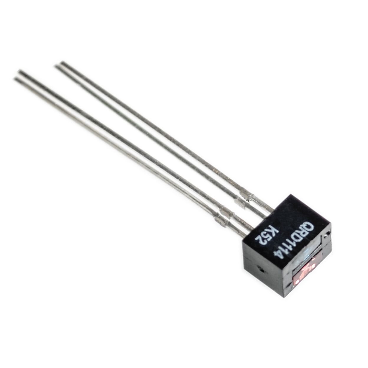
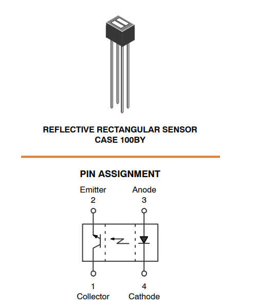
The QRD1114 is a compact, through-hole reflective sensor combining an infrared (IR) emitting diode and an NPN phototransistor in a single package. When a reflective object is placed in front of the sensor, the emitted IR light reflects back to the phototransistor, which then conducts current. This output current is proportional to the reflectivity of the object and the distance (D) from the sensor face. The device is Pb-free, RoHS compliant, and features a daylight filter to reduce ambient light interference.

2. Application Example: Object Detection for a Conveyor Belt
In an industrial automation scenario, the QRD1114 can be used to detect passing packages on a conveyor belt. The sensor is mounted close to the belt surface. According to the datasheet, the optimal sensing distance (D) is 0.050 inches (1.27 mm) from the sensor face to the reflective surface. When a package passes at this distance, the reflected IR light increases, driving the phototransistor's collector current above a set threshold, signaling the presence of an object. This signal can then be used to trigger a counter, activate a diverter, or log a timestamp.

3. Circuit Design and Interface
The phototransistor operates as a current sink. A simple interface circuit uses a pull-up resistor (RL) to convert the collector current (IC) into a voltage (VOUT) readable by a microcontroller's analog-to-digital converter (ADC) or a digital input with a comparator.
3.1. Schematic Design

3.2. Component Selection
- VCC: 5V (or 3.3V if compatible with the microcontroller's I/O).
- R1 (IR LED current limit): To set IF = 20 mA (typical test condition), R1 = (VCC - VF) / IF. With VF ≈ 1.5V at 20 mA (see Figure 1 in datasheet), R1 ≈ (5V - 1.5V) / 0.02A = 175 Ω. A standard value of 180 Ω is suitable.
- RL (Pull-up resistor): The value determines the output voltage swing. With IC(ON) min = 1 mA at VCE = 5V (tested at D = 0.050 inches), a 4.7 kΩ resistor provides a good trade-off. With object present: VOUT ≈ 5V - (1 mA * 4.7 kΩ) ≈ 0.3V (low). With no object: VOUT ≈ 5V (high, due to dark current being negligible). A 4.7 kΩ resistor is recommended.
- C1: Optional 0.1 µF capacitor for power supply decoupling and noise filtering.
3.3. Firmware Example (Arduino-style pseudocode)
const int sensorPin = A0; // Analog input pin
const int threshold = 200; // ADC threshold (0-1023), adjust based on testing

void setup() {
  Serial.begin(9600);
  pinMode(sensorPin, INPUT);
}

void loop() {
  int sensorValue = analogRead(sensorPin);
  // In the circuit above, Vout is LOW when object is present
  if (sensorValue < threshold) {
    Serial.println("Object detected!");
    // Trigger an action, e.g., increment counter, activate a relay
  } else {
    Serial.println("No object");
  }
  delay(100);
}
4. Performance and Optimization Considerations
Based on the datasheet, several factors affect the sensor's output. The most critical is the sensing distance (D):
- Optimal Sensing Distance: The datasheet specifies performance at D = 0.050 inches (1.27 mm). As shown in Figure 2, the output current decreases sharply as distance increases beyond this point. For reliable detection, the sensor should be positioned as close to this optimal distance as possible.
- Reflectivity of Object: The IC(ON) specification (1 mA min) is measured using a 90% reflective white test card. Darker or matte surfaces produce a weaker signal. Thresholds may need to be tuned for the specific target material.
- Temperature: Figure 3 in the datasheet shows that the collector current is fairly stable over temperature, but dark current (Figure 4) increases with temperature. This may affect threshold settings at high temperatures.
- Ambient Light: The built-in daylight filter reduces, but does not eliminate, the effect of ambient IR light. In high-ambient environments, modulation techniques (e.g., pulsing the LED and using synchronous detection) can improve noise immunity.
- Cross Talk: The ICX (cross talk) specification (0.2 µA typical) is the collector current with no reflective surface. This should be considered in the threshold design.

5. Conclusion
The QRD1114 is a versatile and cost-effective solution for non-contact object detection in a wide range of applications, with an optimal sensing range of 1.27 mm (0.050 inches). By understanding its electrical characteristics and following the design guidelines in this article, engineers can quickly integrate this sensor into robust and reliable systems. Always refer to the latest datasheet for complete specifications and design constraints.
References: onsemi QRD1114/D Reflective Object Sensor Datasheet, December 2024 – Rev. 5.
Imágenes
Recursos y referencias
Aún no hay recursos.
Archivos📁
No hay archivos disponibles.


![[4 pc] FAN7371 MOSFET IGBT 4A 600V Gate Driver HIGH SIDE FAN7371MX](https://i.ebayimg.com/images/g/e2IAAOSwFgJmNM0J/s-l225.jpg)