Controlling DC Motors with the TB6612FNG and Arduino
In this tutorial, we will learn how to control the speed and direction of DC motors using the TB6612FNG motor driver module. This setup will allow us to drive two motors independently, providing a practical way to build wheeled robots or mechanized projects. Additionally, we will explore how to use Pulse Width Modulation (PWM) to accurately control the speed of each motor, enhancing your project's movement capabilities.
Throughout this guide, we will be using an Arduino board along with the TB6612FNG breakout board and two DC gear motors. The TB6612FNG is a massive upgrade over older bipolar drivers like the L298N because it uses high-efficiency MOSFETs. This is particularly useful in battery-powered applications where durability and power efficiency are required, since this driver delivers more power to the motors without overheating or requiring a massive heatsink.
For further clarification on the setup and programming, be sure to check the associated video at (in video at 00:00).
Hardware Explained
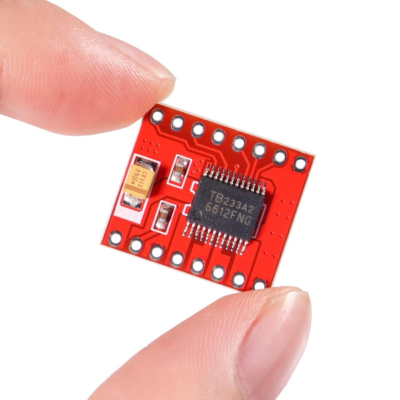
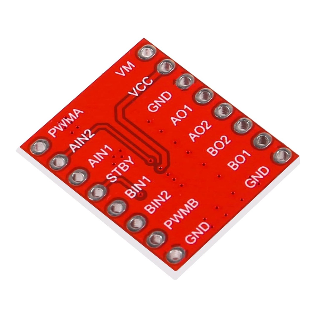
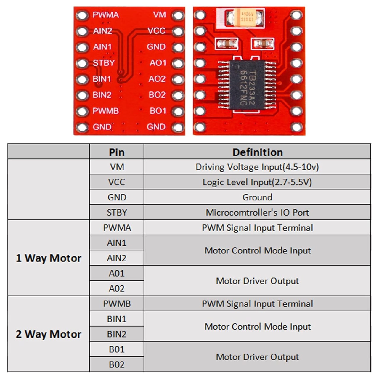
The primary components in this project include the TB6612FNG motor driver, a microcontroller (Arduino), and two DC motors. The TB6612FNG driver takes low-current logic signals from the Arduino and uses them to switch high-current power from a battery to the motors. It typically has dedicated pins for logic power, motor power, direction control (AIN1, AIN2, BIN1, BIN2), and speed control (PWMA, PWMB).
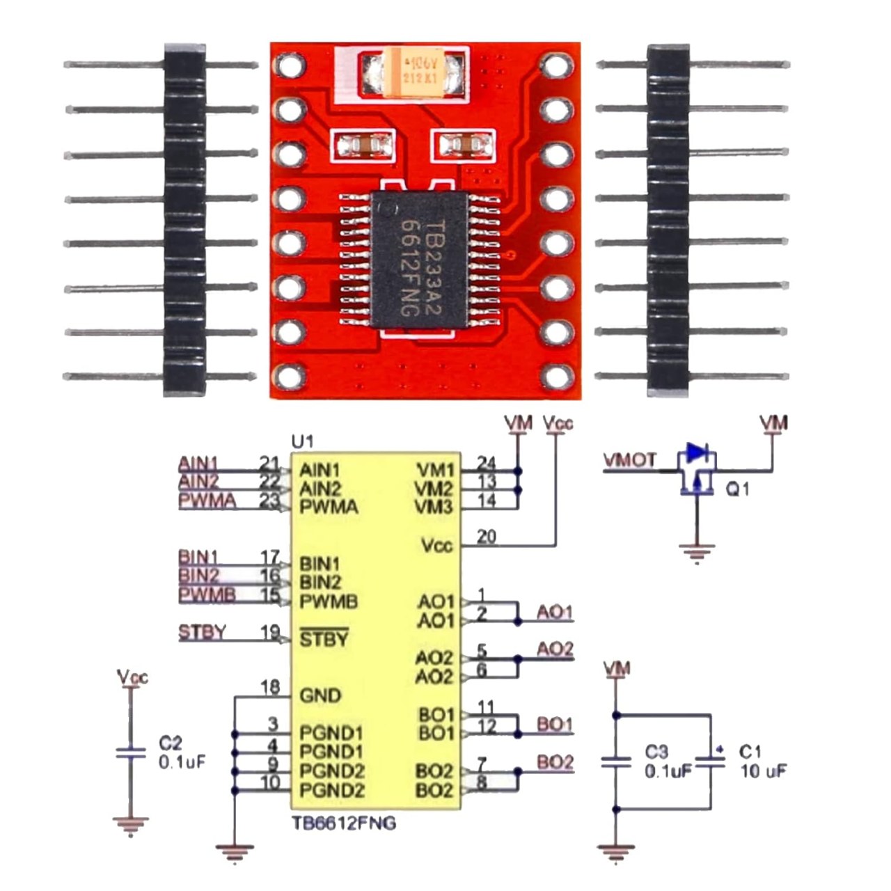
The DC motors receive the modulated power from the driver's output pins (A01/A02 and B01/B02) to rotate. The standby pin (STBY) acts as a master switch, providing a quick way to disable the motors and put the chip into a low-power sleep state. Each component plays a crucial role in ensuring the drive system works smoothly and efficiently.
Datasheet Details
|
Manufacturer |
Toshiba (IC) / Various (Module) |
|---|---|
|
Part number |
TB6612FNG |
|
Logic/IO voltage |
2.7 V to 5.5 V |
|
Supply voltage (VM) |
2.7 V to 15 V |
|
Output current (per channel) |
1.2 A continuous |
|
Peak current (per channel) |
3.2 A |
|
PWM frequency guidance |
Up to 100 kHz |
|
Input logic thresholds |
High: > 2.0V, Low: < 0.8V (at 5V VCC) |
|
Voltage drop / RDS(on) / saturation |
0.5 Ω (typical) |
|
Thermal limits |
Thermal shutdown circuit built-in |
|
Package |
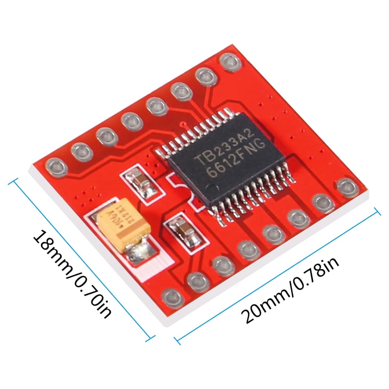
SSOP24 / Breakout Board |
|
Notes / variants |
Replaces the L298N with much higher efficiency. |
-
Ensure proper voltage levels (match VCC to your Arduino's 5V or ESP32's 3.3V).
-
Provide a separate battery power supply for the VM (Motor Power) pin.
-
Be cautious to tie all grounds (battery, Arduino, and module) together to prevent erratic behavior.
-
Test connections before powering up to prevent short circuits.
-
Always pull the STBY pin HIGH, or the motors will not run.
Wiring Instructions
Begin by connecting the power and ground for all components. Connect the ground from your Arduino to the negative rail of your breadboard. Then, connect your external battery's positive lead to the VM pin on the motor driver, and the Arduino's 5V pin to the VCC pin on the driver.
Next, wire the logic inputs: connect AIN1 to digital pin 2 on the Arduino, AIN2 to digital pin 4, and PWMA to a PWM-capable pin, such as digital pin 5. For the second motor, connect BIN1 to 7, BIN2 to 8, and PWMB to pin 6. Make sure to connect the STBY pin to digital pin 9.
For the output to the motors, connect the two terminals of your first DC motor to A01 and A02. Connect your second DC motor to B01 and B02. Double-check that all grounds are shared on the common ground rail.
Code Examples & Walkthrough
Let’s take a look at some key identifiers and code snippets used in the project. The first part of the code initializes the pins for the direction control, speed, and standby:
const int AIN1 = 2;const int AIN2 = 4;const int PWMA = 5;const int STBY = 9;Here, AIN1 and AIN2 are assigned to control the direction of Motor A, while PWMA will be used for speed control via PWM. STBY allows the Arduino to wake the chip up or put it to sleep.
Next, the setup function configures these pins as outputs and enables the chip:
void setup() { pinMode(AIN1, OUTPUT); pinMode(AIN2, OUTPUT); pinMode(PWMA, OUTPUT); pinMode(STBY, OUTPUT); // Enable the motor driver digitalWrite(STBY, HIGH);}The pinMode() commands set the pins to output mode. Setting STBY to HIGH ensures the TB6612FNG is active and ready to receive commands.
In the loop function, we command the motor to spin forward at full speed, stop, and then reverse:
void loop() { // Forward at full speed digitalWrite(AIN1, HIGH); digitalWrite(AIN2, LOW); analogWrite(PWMA, 255); delay(2000); // Stop (Coast) digitalWrite(AIN1, LOW); digitalWrite(AIN2, LOW); analogWrite(PWMA, 0); delay(1000);}Here, setting AIN1 HIGH and AIN2 LOW tells the internal H-bridge to push current in one direction. analogWrite(PWMA, 255) applies maximum speed. To stop, we pull both direction pins LOW.
For further details and the complete code featuring dual motor control and custom functions, please refer to the full program loaded below the article.
Demonstration / What to Expect
Once the wiring is complete and the code is uploaded, you should see the motor spin forward for two seconds, pause for one second, and repeat the cycle (if you added the reverse logic, it will spin backward next). Ensure the motor responds correctly to the PWM signals; if it spins backward when you expect it to go forward, simply swap the wires connected to A01 and A02 (in video at 12:30).
Common pitfalls include forgetting to pull the STBY pin HIGH, or trying to power the motors directly from the Arduino's 5V pin instead of a dedicated battery on the VM pin, which can cause the Arduino to reset under heavy load. Be sure to double-check your power sources and shared grounds.
تصاویر
مواردی که ممکن است به آنها نیاز داشته باشید
-
آمازون
-
آمازونBuy TB6612FNG or DRV8833 motor driver board from AliExpresss.click.aliexpress.com
منابع و مراجع
هنوز هیچ منبعی موجود نیست.
فایلها📁
برگه مشخصات (pdf)
-
motor driver TB6612FNG datasheet
motor_driver_TB6612FNG_datasheet.pdf0.20 MB