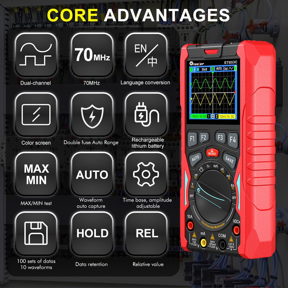
AV ToolTop ET853C Scope Meter Review and Practical Demonstration
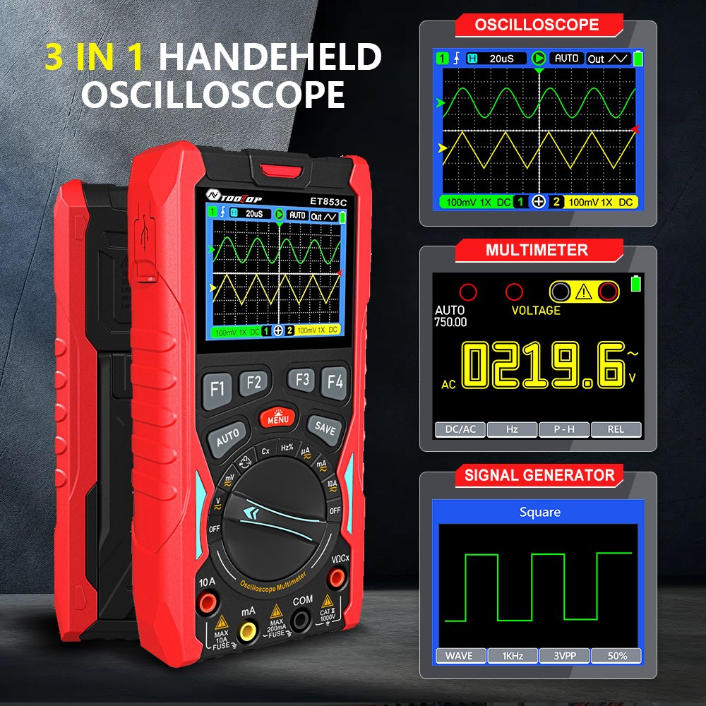
this article, we take a close look at the AV ToolTop ET853C Scope Meter, a compact all-in-one test instrument that combines a digital multimeter, oscilloscope, and waveform (function) generator into a single rechargeable handheld device.
This article is based on the accompanying YouTube video (embedded above). Where helpful, I refer to specific moments in the video so you can visually follow along.

Overview: What Is the AV ToolTop ET853C?
At the beginning of the video (00:00–00:20), the ET853C is introduced as a surprisingly compact scope meter with a built-in rechargeable battery. Despite its small size, it integrates:
- Digital Multimeter (DMM)
- Two-channel Oscilloscope
- Waveform / Function Generator
This makes it an excellent tool for electronics hobbyists, students, and engineers who want portability without sacrificing essential measurement features.
What’s Included in the Box
Around 01:10–02:00 in the video, the box contents are shown. Inside, you get:
- The ET853C scope meter unit
- USB-C charging cable
- Two oscilloscope probes
- Color-coded probe rings
- Probe adjustment screwdriver
- User manual
Everything needed to start measuring right away is included.
Physical Layout and Connections
At 02:15–02:30, the device layout is explained:
- USB-C port on top for charging
- Two oscilloscope input connectors (Channel 1 and Channel 2)
- Dedicated terminals for multimeter measurements
- Center terminal for the function generator output
The charging indicator LED turns red while charging and green when fully charged (05:35–05:45).
Understanding the Multimeter Interface
From 02:30 onward, the multimeter interface is demonstrated. The screen uses soft-keys (F1, F2, etc.), where each on-screen label corresponds to the physical button directly below it.
Key multimeter features include:
- AC and DC voltage
- Microamp, milliamp, and ampere current
- Resistance and continuity
- Capacitance
- Frequency and duty cycle
- Diode and transistor testing
A very helpful feature shown around 04:00–04:40 is the visual terminal guide. The screen clearly shows which terminals you should connect your probes to, reducing the chance of mistakes.
Measuring Voltage and Resistance
At 07:20–08:30, DC voltage measurement is demonstrated. The meter automatically selects the range, but you can switch between auto and manual ranging if needed.
Resistance measurements are shown shortly after (08:30–08:50), including both low-ohm and kilo-ohm values, with stable and accurate readings.
Measuring Current Safely
Starting around 08:50, current measurement is explained in detail. The video emphasizes an important safety point:
Current must always be measured in series with the load. Connecting the meter directly across a power source in current mode will blow the internal fuse.
The ET853C supports:
- Microamp measurements
- Milliamp measurements
- Up to 10A current (fused)
Ohm’s Law is applied in the video (11:15–12:30) to verify measured current against calculated values, demonstrating the accuracy of the device.
Data Hold and Internal Storage
One standout feature shown at 10:20–10:50 is the ability to save measurements internally. The ET853C can store up to around 2000 records, which can later be recalled from the data menu.
This is extremely useful when comparing measurements or documenting results.
AC Voltage, Frequency, and Duty Cycle
At 15:20–16:10, AC line measurements are demonstrated:
- AC voltage (≈117V shown)
- Line frequency (≈60Hz)
- Duty cycle (~50%)
Switching between these modes is quick and intuitive using the function buttons.
Capacitance, Diode, and Transistor Testing
From 16:15–18:40, the ET853C is used to:
- Measure electrolytic and small ceramic capacitors
- Test diodes with forward voltage drop
- Check transistor junctions (example: 2N2222)
The clear on-screen instructions make these tests easy even for beginners.
Built-In Function Generator
At 18:45–20:05, the built-in waveform generator is activated. It supports:
- Square wave
- Sine wave
- Ramp (triangle) wave
You can adjust:
- Frequency (up to several MHz)
- Amplitude
- Duty cycle
This makes the ET853C especially useful for testing circuits without needing an external signal generator.
Using the Oscilloscope Mode
From 20:05 onward, the oscilloscope mode is demonstrated using the internal function generator as a signal source.
Key oscilloscope features include:
- Two channels
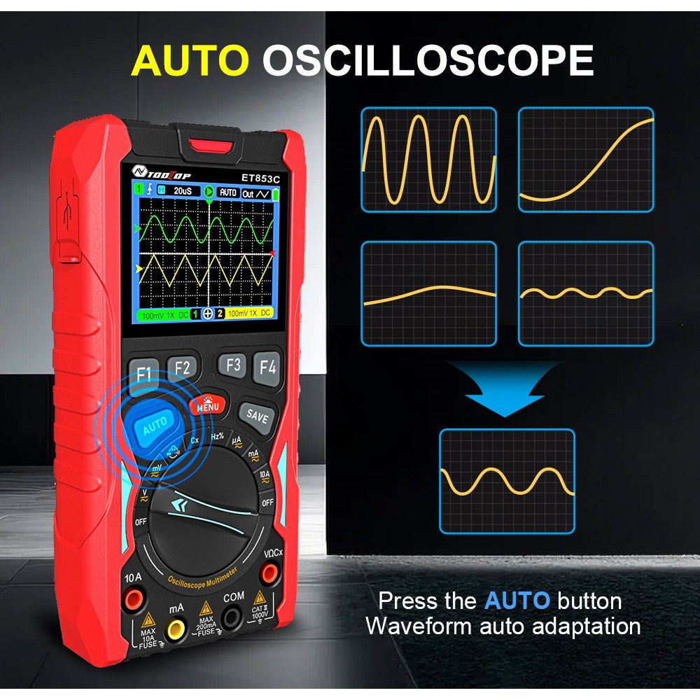
- Auto-set function for quick waveform capture
- Adjustable time base and voltage scale
- Clear color display
The video shows how changing the time scale affects waveform visibility and how the auto function quickly stabilizes the signal on screen.
Final Verdict
In the conclusion (22:40–end), the ET853C is described as one of the best values available in its price range (around $80).
Key advantages include:
- Rechargeable battery (no disposable batteries)
- Color display with intuitive UI
- Multimeter, oscilloscope, and function generator in one device
- Data storage and waveform saving
|
AV ToolTop ET853C Specifications
Note: The following specifications are taken from the ET853C specification PDF. :contentReference[oaicite:0]{index=0}
General Characteristics
| Item | Specification | Item | Specification |
|---|---|---|---|
| Display | 320×240 TFT color screen | Viewing Area | 49.0mm × 36.7mm |
| Backlight Brightness | Adjustable | Input Impedance | 10MΩ |
| Battery | 18650 lithium battery | Auto Sleep | 5–60 minutes (or disabled) |
| Standby Current | < 0.3A | Power-off Current | < 5µA |
| Continuous Use Time | Approx. 4 hours | Storage Capacity | 1000 DMM records, 200 osc waveform records |
| Operating Environment | 0°C to +40°C, < 75%RH | Storage Conditions | -10°C to +60°C, < 90%RH |
| Dimensions | 83mm × 160mm × 32mm | Weight | About 220g |
| Charging Standard | 5V | Charging Port | Type-C |
Oscilloscope Specifications
| Item | Specification | Item | Specification |
|---|---|---|---|
| Analog Bandwidth | 70MHz (single channel), 40MHz (dual channel) | Max. Equivalent Sampling Rate | 200MSps |
| Number of Channels | 2 | Input Impedance | Approx. 1MΩ |
| Vertical Sensitivity Range | 50mV/div to 10V/div | Time Base Range | 6ns/div to 50s/div |
| Vertical Amplitude Accuracy | ±(5% + 0.2div) | Time Base Accuracy | ±(0.01% + 0.1div) |
| Scan Modes | Auto / Normal / Single | Trigger Edge Selection | Rising / Falling |
| Coupling Modes | DC / AC | Auto Setup | Automatically sets time base and vertical amplitude |
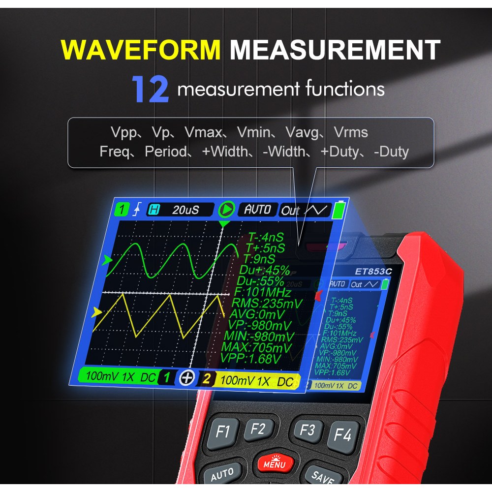
| Voltage Measurement | Vpp, Vp, Vmax, Vmin, Vavg, Vrms | Time Measurement | Freq, Period, +Width, -Width, +Duty, -Duty |
Signal Generator Specifications
| Item | Specification |
|---|---|
| Output Frequency (Sine) | 10Hz to 100kHz (stepped in 1–2–3–5 sequence) |
| Output Frequency (Triangle) | 10Hz to 100kHz (stepped in 1–2–3–5 sequence) |
| Output Frequency (Square) | 10Hz to 3MHz (stepped in 1–2–3–5 sequence) |
| Output Amplitude | 3Vpp, 2Vpp, 1Vpp, 0.5Vpp, 0.2Vpp, 0.1Vpp, 0Vpp |
Digital Multimeter (DMM) Specifications
Accuracy format in the PDF is expressed as: ±(% of reading + number of digits), with stated calibration validity of 1 year, based on 23°C ± 5°C and < 75% RH. :contentReference[oaicite:1]{index=1}
| Function | Range | Resolution | Accuracy |
|---|---|---|---|
| DC Voltage | 2V / 20V / 200V / 1000V | 0.1mV / 1mV / 10mV / 100mV | ±0.5%rdg + 5dgt (2V–200V), ±1%rdg + 8dgt (1000V) |
| DC Voltage | 20.000mV / 200.00mV | 0.001mV / 0.01mV | ±0.5%rdg + 10dgt |
| AC Voltage (True RMS) | 2V / 20V / 200V / 750V | 0.1mV / 1mV / 10mV / 100mV | ±1%rdg + 10dgt (50Hz–1kHz) |
| AC Voltage (True RMS) | 20.000mV / 200.00mV | 0.001mV / 0.01mV | ±1%rdg + 10dgt (50Hz–1kHz) |
| DC Current | 200.00µA / 2000.0µA | 0.01µA / 0.1µA | ±0.8%rdg + 8dgt |
| DC Current | 20.000mA / 200.00mA | 1µA / 10µA | ±0.8%rdg + 8dgt |
| DC Current | 2A / 10A | 0.1mA / 1mA | ±0.8%rdg + 8dgt |
Other DMM Ranges (from the spec sheet)
| Function | Range / Notes |
|---|---|
| AC Current (True RMS) | 200.00µA / 2000.0µA, 20.000mA / 200.00mA, 2A / 10A |
| Resistance | 200Ω / 2kΩ / 20kΩ / 200kΩ / 2MΩ / 20MΩ / 200MΩ (values above 50MΩ are for reference only) |
| Capacitance | 9.999nF / 99.99nF / 999.9nF / 9.999µF / 99.99µF / 999.9µF, plus 9.999mF / 99.99mF |
| Frequency | 1.000Hz to 20.000MHz (above 20M for reference only) |
| Diode Test | Open-circuit voltage approx. (per spec sheet) |
| Continuity Test | Threshold resistance approx. (per spec sheet) |
| Fuse Ratings | 200mA / 250V, 10A / 125V |
Compared to much more expensive standalone instruments, the AV ToolTop ET853C delivers impressive performance and versatility in a very portable form factor.
Affiliate links to purchase the AV ToolTop ET853C are available below this article.
图像

|||您可能需要的东西
-
亚马逊在亚马逊上购买AV工具Top ET853Camzn.to
-
易趣在eBay购买AV ToolTop ET853Cebay.us
-
全球速卖通从AliExpress购买AV工具Top ET853Cs.click.aliexpress.com
-
全球速卖通从AliExpress(官方商店)购买AV工具Top ET853Cs.click.aliexpress.com
-
Banggood从Banggood购买AV工具Top ET853Cbanggood.com
资源与参考
尚无可用资源。
文件📁
用户手册
-
AV_ToolTOP_ET853C 3合1仪表_用户手册
AV_ToolTOP_ET853C_meter_user_manual.pdf2.96 MB