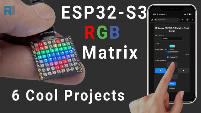
This tutorial is part of: ESP32-S3 RGB LED Matrix
Cool project to create for fun and practical applications using ESP32-S3 RGB Matrix module. Links to other videos are below this article.
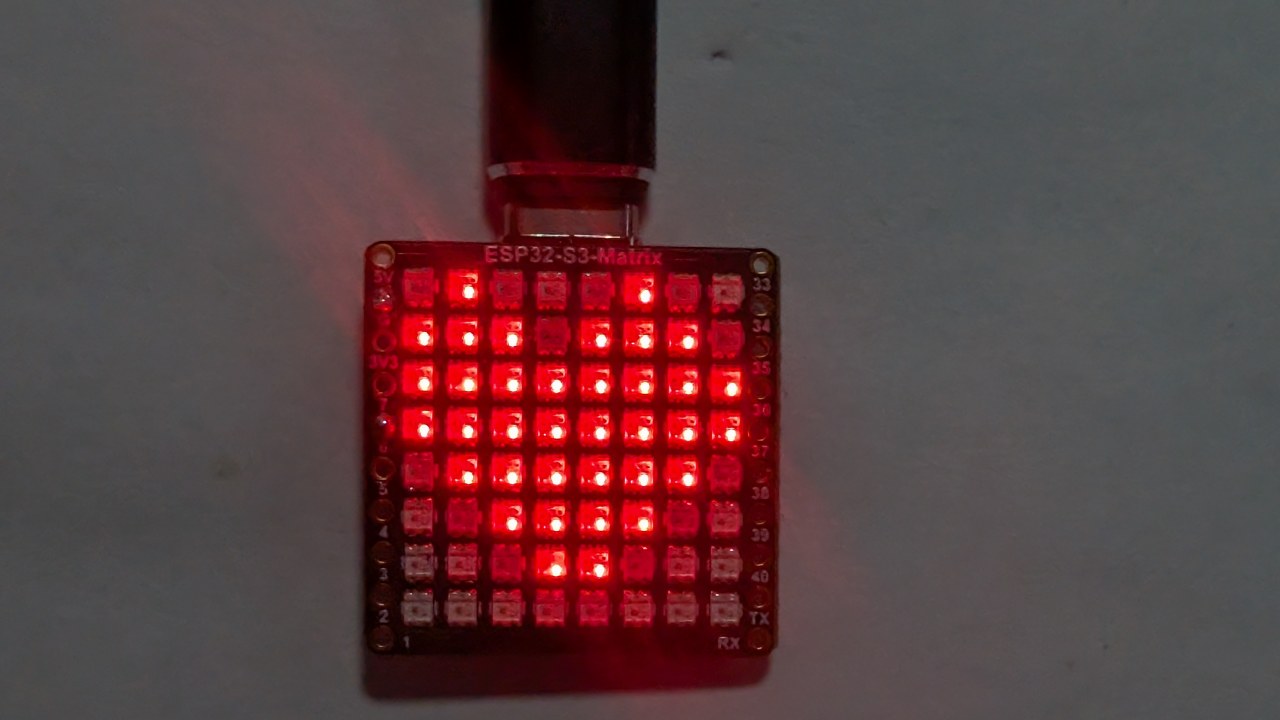
ESP32-S3 RGB LED Matrix Project 5 - Arrow always up
Project 5 – Arrow Always Up (Orientation Indicator using QMI8658C)
Project 5 uses the QMI8658C motion sensor to detect the orientation of the ESP32-S3 RGB LED Matrix and always display an arrow pointing UP relative to gravity. No matter how you rotate the board—USB side up, OUSB side up, side “15”, or side “34”—the arrow automatically turns and points toward the physically upward direction.
This is a powerful demonstration of real-time orientation sensing using the onboard accelerometer. All six projects for this module are demonstrated in one YouTube video, which is also embedded on this page. The complete code for Project 5 loads automatically below the article, and affiliate links appear under the code section.

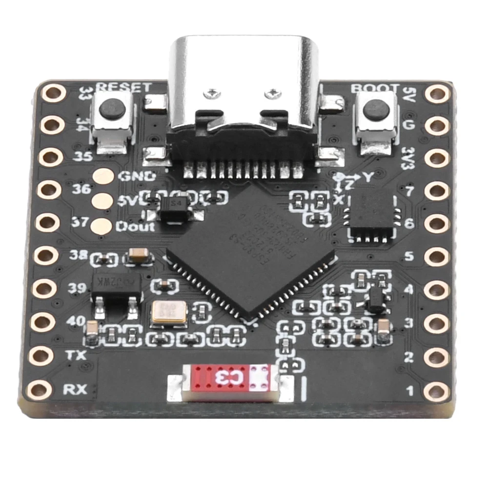
ESP32-S3 RGB LED Matrix Module Overview
The ESP32-S3 RGB LED Matrix module includes several components that make this project possible:

- ESP32-S3 microcontroller — provides Wi-Fi, BLE, and runs the LED/IMU logic.
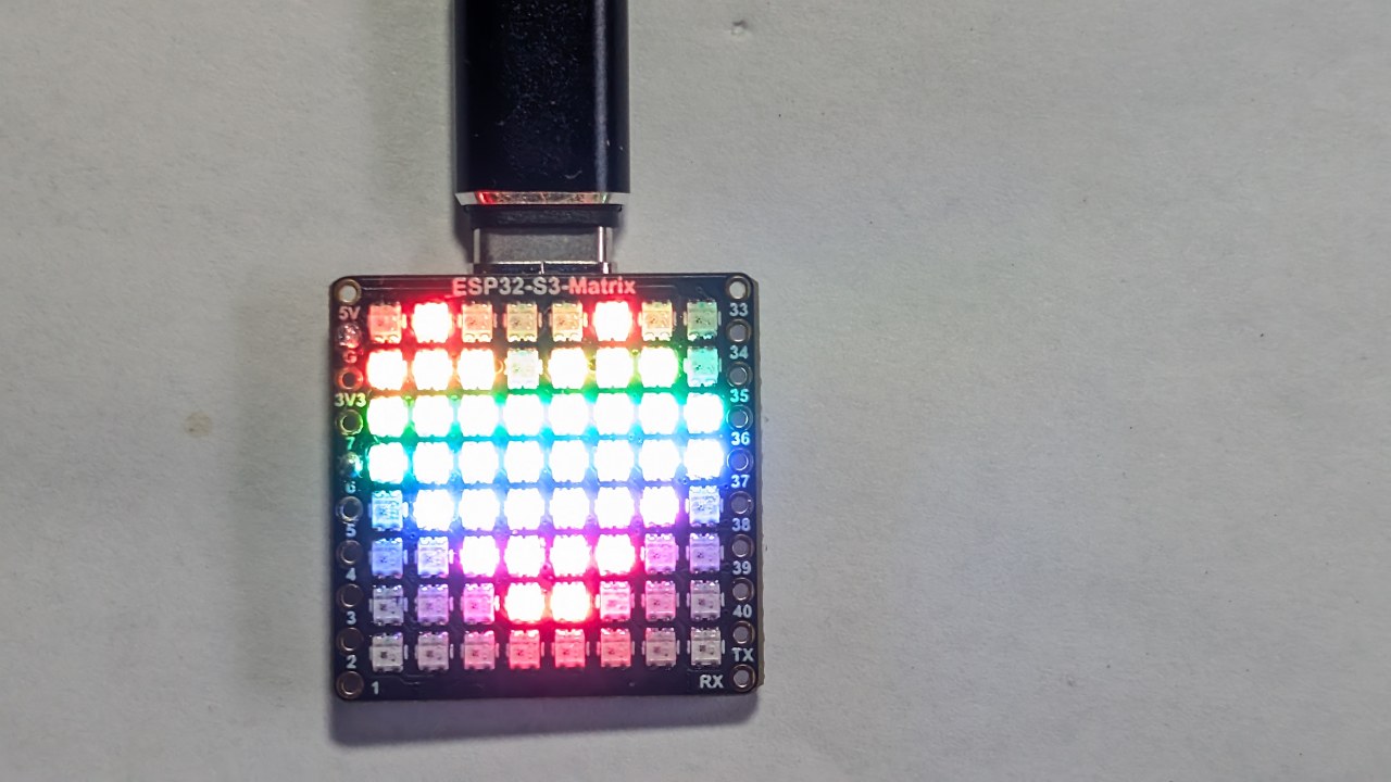
- 8×8 RGB LED matrix — displays the arrow in any of four orientations.
- QMI8658C accelerometer — detects tilt, movement, and orientation.:contentReference[oaicite:0]{index=0}
- USB-C port for power and programming in Arduino IDE.
- Reset and Boot buttons for uploading sketches.
- GPIO pins available around the board for additional projects.
The arrow direction is determined entirely by the accelerometer readings. When the board is rotated, the QMI8658C senses the new X/Y/Z values, and the sketch chooses which arrow pattern (↑, ↓, ←, →) should be drawn.

Projects Covered in the Video (Timestamps)
- 00:00 – Introduction
- 02:01 – Installing ESP32 boards
- 03:32 – Installing libraries
- 05:32 – Project 1: Moving Dot
- 11:11 – Project 2: Text Scroll
- 12:59 – Project 3: HTTP Text
- 16:41 – Project 4: Tilt Dot
- 18:55 – Project 5: Arrow Always Up (this project)
- 20:02 – Project 6: Target Game
The video clearly shows how the arrow changes direction instantly based on how the module is turned. Watching this segment is strongly recommended.:contentReference[oaicite:1]{index=1}

Installing ESP32 Boards in Arduino IDE
If you completed any earlier project, the board setup is already done. Otherwise:
File > Preferences→ Add ESP32 board URLTools > Board > Boards Manager…→ Install “ESP32”- Select the ESP32-S3 board under
Tools > Board - Select the correct USB COM port under
Tools > Port
Installing Required Libraries
Project 5 uses:
Adafruit NeoMatrixAdafruit NeoPixelAdafruit GFXQMI8658(motion sensor)
Sketch > Include Library > Manage Libraries…- Search: NeoMatrix → Install
- Install dependencies: NeoPixel + GFX
- Search and install QMI8658 by its author
How Project 5 Works
The QMI8658C measures gravity on X, Y, and Z axes. By comparing these values, the sketch determines which physical side of the board is facing upward:
- USB side up
- OUSB side up (opposite USB)
- Side “15” up
- Side “34” up
Each orientation corresponds to a different arrow pattern on the 8×8 matrix. The mapping follows your confirmed orientation logic from earlier debugging sessions. The board’s rotation is read continuously, and the arrow updates as soon as the upward side changes.
Project 5 – Code Settings (Arrow Always Up)
Below are the user-adjustable values from the configuration area. The full project code appears automatically below the article.
Matrix Configuration
// Matrix configuration
const int MATRIX_PIN    = 14;   // fixed for this module
const int MATRIX_WIDTH  = 8;
const int MATRIX_HEIGHT = 8;

// Recommended orientation: Top-Left origin, progressive mode
// (actual constructor is inside the code loaded below)
This project uses NEO_MATRIX_PROGRESSIVE layout to ensure the arrow points correctly based on actual movement.
Brightness
uint8_t matrixBrightness = 40; // 0–255
You may raise this value for brighter environments. For indoor use, 30–60 is comfortable.
Arrow Color
// Arrow color
uint8_t arrowRed   = 255;
uint8_t arrowGreen = 0;
uint8_t arrowBlue  = 0;
Change these values to modify the arrow’s color. For example:
- Green arrow:
(0, 255, 0) - Blue arrow:
(0, 0, 255) - White arrow:
(255, 255, 255)
Sensitivity and Smoothing
To avoid jitter, the code includes smoothing and threshold logic. In the settings you may find something like:
// Sensitivity / smoothing adjustment
float tiltThreshold = 0.30f;   // adjust if arrow changes too easily
- If your arrow flips too easily → increase threshold.
- If arrow is too slow to change → decrease threshold.
Arrow Patterns
The sketch includes arrow bitmap patterns for:
- ↑ up
- ↓ down
- ← left
- → right
You do not need to modify these, but you can change the shapes inside the code if you want a different style.
Summary
Project 5 demonstrates how the ESP32-S3 RGB LED Matrix and the QMI8658C accelerometer work together to detect orientation and display an arrow that always points upward. This project builds on the Tilt Dot (Project 4) and prepares you for the final interactive game in Project 6.
The full “Arrow Always Up” sketch is available below this article (auto-loaded). Watching the corresponding part of the video is highly recommended to see how instantly the arrow responds to board rotation. If you wish to build this project at home, affiliate links for the ESP32-S3 RGB LED Matrix module appear under the code section.
Images


This tutorial is part of: ESP32-S3 RGB LED Matrix
- ESP32-S3 RGB LED Matrix Project 1- Basic Dot
- ESP32-S3 RGB LED Matrix Project 2 - Scrolling Text
- ESP32-S3 RGB LED Matrix Project 3 - Text from mobile phone
- ESP32-S3 RGB LED Matrix Project 4 - Tilt dot
- ESP32-S3 RGB LED Matrix Project 6 - Cible game
- ESP32-S3 RGB LED Matrix Wi-Fi + NTP Time Clock Project -1 Basic Clock
- ESP32-S3 RGB LED Matrix Internet Clock Project - 2 Clock multi color Time & Date Display
- ESP32-S3 RGB LED Matrix Internet Clock Project - 3 Night Color with Date
- ESP32-S3 RGB LED Matrix Internet Clock Project - 5 Rainbow color
- ESP32-S3 RGB LED Matrix Internet Clock Project - 4 Random color
- ESP32-S3 RGB LED Matrix test for RGB, GRB setting
/*
  Project 5: Arrow Always Up – ESP32-S3 RGB LED Matrix (Waveshare)
  This sketch reads tilt from the QMI8658C IMU and smoothly moves a dot
  on the 8×8 RGB LED matrix based on board orientation.

  ▶️ Video Tutorial:
  https://youtu.be/JKLuYrRcLMI

  📚⬇️ Resources & Code Page:
  https://robojax.com/RJT833

  QMI8658_RGB_2
*/
#include <Arduino.h>
#include <math.h>

#include <Adafruit_GFX.h>
#include <Adafruit_NeoMatrix.h>
#include <Adafruit_NeoPixel.h>

#include <QMI8658.h>   // by Lahav Gahali

// -------- LED MATRIX SETUP --------
#define MATRIX_PIN    14
#define MATRIX_WIDTH  8
#define MATRIX_HEIGHT 8

Adafruit_NeoMatrix matrix = Adafruit_NeoMatrix(
  MATRIX_WIDTH, MATRIX_HEIGHT, MATRIX_PIN,
  NEO_MATRIX_TOP + NEO_MATRIX_LEFT +
  NEO_MATRIX_ROWS + NEO_MATRIX_PROGRESSIVE,
  NEO_RGB + NEO_KHZ800
);

// -------- QMI8658 IMU SETUP --------
QMI8658 imu;
QMI8658_Data imuData;

// -------- USER SETTINGS --------

// true  -> arrow points to opposite side
//         USB↔OUSB, 34↔15
// false -> arrow points to the same side that is UP
bool useOppositeMapping = false;

// Arrow color (0–255 each)
uint8_t dotRed   = 0;
uint8_t dotGreen = 150;
uint8_t dotBlue  = 0;

// Board sides
enum Side {
  SIDE_CENTER = 0,
  SIDE_USB,
  SIDE_OUSB,
  SIDE_15,
  SIDE_34
};

// Direction for arrow drawing
enum ArrowDir {
  ARROW_CENTER,
  ARROW_UP,
  ARROW_DOWN,
  ARROW_LEFT,
  ARROW_RIGHT
};

bool isFlat = false;

const char* sideName(Side s) {
  switch (s) {
    case SIDE_CENTER: return "CENTER";
    case SIDE_USB:    return "USB";
    case SIDE_OUSB:   return "OUSB";
    case SIDE_15:     return "15";
    case SIDE_34:     return "34";
    default:          return "?";
  }
}

// -------- ARROW DRAWING (YOUR CODE, UNCHANGED) --------

// Draw a simple arrow on 8x8 matrix pointing in the given direction
void drawArrow(ArrowDir dir, uint16_t color) {
  matrix.fillScreen(0);

  switch (dir) {
    case ARROW_UP:
      // Tip
      matrix.drawPixel(3, 0, color);
      matrix.drawPixel(4, 0, color);
      // Second row
      matrix.drawPixel(2, 1, color);
      matrix.drawPixel(3, 1, color);
      matrix.drawPixel(4, 1, color);
      matrix.drawPixel(5, 1, color);
      // Shaft
      matrix.drawLine(3, 2, 3, 6, color);
      matrix.drawLine(4, 2, 4, 6, color);
      break;

    case ARROW_DOWN:
      // Tip
      matrix.drawPixel(3, 7, color);
      matrix.drawPixel(4, 7, color);
      // Row above tip
      matrix.drawPixel(2, 6, color);
      matrix.drawPixel(3, 6, color);
      matrix.drawPixel(4, 6, color);
      matrix.drawPixel(5, 6, color);
      // Shaft
      matrix.drawLine(3, 1, 3, 5, color);
      matrix.drawLine(4, 1, 4, 5, color);
      break;

    case ARROW_LEFT:
      // Tip
      matrix.drawPixel(0, 3, color);
      matrix.drawPixel(0, 4, color);
      // Column after tip
      matrix.drawPixel(1, 2, color);
      matrix.drawPixel(1, 3, color);
      matrix.drawPixel(1, 4, color);
      matrix.drawPixel(1, 5, color);
      // Shaft
      matrix.drawLine(2, 3, 6, 3, color);
      matrix.drawLine(2, 4, 6, 4, color);
      break;

    case ARROW_RIGHT:
      // Tip
      matrix.drawPixel(7, 3, color);
      matrix.drawPixel(7, 4, color);
      // Column before tip
      matrix.drawPixel(6, 2, color);
      matrix.drawPixel(6, 3, color);
      matrix.drawPixel(6, 4, color);
      matrix.drawPixel(6, 5, color);
      // Shaft
      matrix.drawLine(1, 3, 5, 3, color);
      matrix.drawLine(1, 4, 5, 4, color);
      break;

    case ARROW_CENTER:
    default:
      // Simple plus in the center
      matrix.drawLine(3, 3, 4, 3, color);
      matrix.drawLine(3, 4, 4, 4, color);
      matrix.drawLine(3, 3, 3, 4, color);
      matrix.drawLine(4, 3, 4, 4, color);
      break;
  }

  matrix.show();
}

// -------- IMU → SIDE DETECTION --------
// We calibrated earlier:
//  +X = USB,   -X = OUSB
//  +Y = 15,    -Y = 34    (after your correction)

Side detectSideUp(float ax_g, float ay_g, float az_g) {
  // Flat detection
  const float flatThreshXY = 0.15f;
  const float flatThreshZ  = 0.15f;

  if (fabs(ax_g) < flatThreshXY &&
      fabs(ay_g) < flatThreshXY &&
      fabs(az_g - 1.0f) < flatThreshZ) {
    isFlat = true;
    return SIDE_CENTER;
  }
  isFlat = false;

  // Thresholds to say "this axis is really tilted"
  const float tiltThreshY = 0.5f;
  const float tiltThreshX = 0.5f;

  // Prefer Y axis for 15 / 34
  if (fabs(ay_g) >= tiltThreshY) {
    if (ay_g > 0) {
      return SIDE_34;   // +Y = 34 up
    } else {
      return SIDE_15;   // -Y = 15 up
    }
  }

  // Otherwise, use X axis for USB / OUSB
  if (fabs(ax_g) >= tiltThreshX) {
    if (ax_g > 0) {
      return SIDE_USB;   // +X = USB up
    } else {
      return SIDE_OUSB;  // -X = OUSB up
    }
  }

  // Not clearly tilted → treat as center
  return SIDE_CENTER;
}

// Map from UP side to where the arrow should point
Side arrowSideFromUpSide(Side upSide) {
  if (!useOppositeMapping) {
    // Arrow shows the side that is UP
    return upSide;
  }

  // Arrow shows the opposite side
  switch (upSide) {
    case SIDE_USB:   return SIDE_OUSB;
    case SIDE_OUSB:  return SIDE_USB;
    case SIDE_15:    return SIDE_34;
    case SIDE_34:    return SIDE_15;
    case SIDE_CENTER:
    default:         return SIDE_CENTER;
  }
}

// Convert SIDE to ArrowDir
ArrowDir arrowDirFromSide(Side s) {
  switch (s) {
    case SIDE_USB:    return ARROW_UP;
    case SIDE_OUSB:   return ARROW_DOWN;
    case SIDE_15:     return ARROW_LEFT;
    case SIDE_34:     return ARROW_RIGHT;
    case SIDE_CENTER:
    default:          return ARROW_CENTER;
  }
}

// ---------------- SETUP & LOOP ----------------

void setup() {
  Serial.begin(115200);
  delay(500);

  matrix.begin();
  matrix.setBrightness(20);
  matrix.fillScreen(0);
  matrix.show();

  // IMU: SDA=11, SCL=12 on ESP32-S3-Matrix
  if (!imu.begin(11, 12)) {
    Serial.println("Failed to initialize QMI8658!");
    while (1) { delay(1000); }
  }

  imu.setAccelUnit_mg(true);
  imu.setGyroUnit_dps(true);
  imu.setDisplayPrecision(4);

  Serial.print("QMI8658 initialized. useOppositeMapping = ");
  Serial.println(useOppositeMapping ? "TRUE" : "FALSE");
}

void loop() {
  if (!imu.readSensorData(imuData)) {
    return;
  }

  float ax_g = imuData.accelX / 1000.0f;
  float ay_g = imuData.accelY / 1000.0f;
  float az_g = imuData.accelZ / 1000.0f;

  Side upSide     = detectSideUp(ax_g, ay_g, az_g);
  Side arrowSide  = arrowSideFromUpSide(upSide);
  ArrowDir dir    = arrowDirFromSide(arrowSide);

  uint16_t color = matrix.Color(dotRed, dotGreen, dotBlue);
  drawArrow(dir, color);

  // Debug
  Serial.print("AX="); Serial.print(ax_g, 3);
  Serial.print(" AY="); Serial.print(ay_g, 3);
  Serial.print(" AZ="); Serial.print(az_g, 3);
  Serial.print(" | UP=");    Serial.print(sideName(upSide));
  Serial.print(" | ARROW="); Serial.println(sideName(arrowSide));

  delay(80);
}
Things you might need
-
Amazon
-
eBay
-
AliExpressPurchase ESP32-S3 RGB Matrix from AliExpresss.click.aliexpress.com
-
AliExpressPurchase ESP32-S3 RGB Matrix from AliExpress (2)s.click.aliexpress.com
Resources & references
-
Internal🎨 Color picker Toolrobojax.com
Files📁
Fritzing File
-
esp32-S3-supermini-tht fritzing part
esp32-S3-supermini-tht.fzpz0.02 MB