Pulse Width Modulation (PMW) Generator XY-LPWM With display to control Servo motor
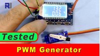
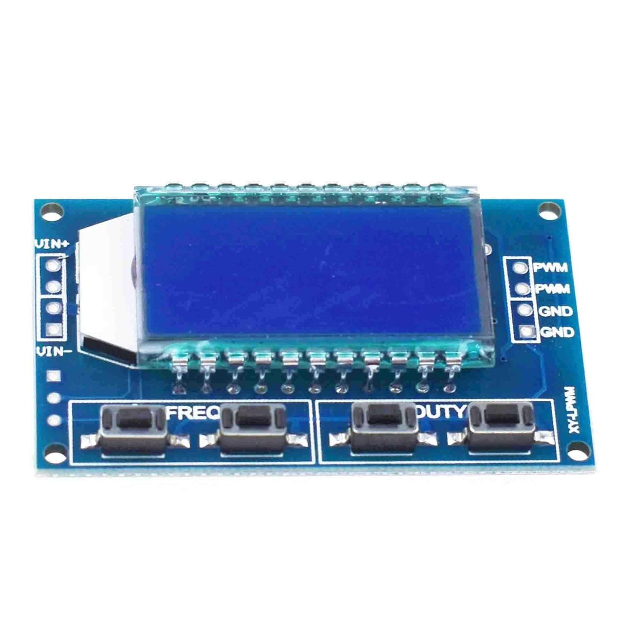
This guide introduces the XY-LPWM, a compact and affordable Pulse Width Modulation (PWM) signal generator. This device is a practical tool for any electronics workbench, allowing you to generate precise square wave signals to control a wide variety of devices. Its primary use case is controlling servo motors, but its functionality extends to any project requiring a variable-frequency, variable-duty-cycle pulse signal.
This module is particularly useful for:
- Testing and calibrating servo motors without writing a single line of code.
- Controlling the speed of DC motors through a motor driver.
- Dimming LEDs for lighting projects or visual indicators.
- Generating test signals for audio circuits or other electronic experiments.
- Serving as an educational tool to visually demonstrate the principles of PWM.
Hardware Overview
The XY-LPWM module is a self-contained signal generator. It features a digital display and four buttons for adjusting the output signal's frequency and duty cycle. The device is powered by a simple 5V supply, making it compatible with Arduino boards, power banks, or standard wall adapters.
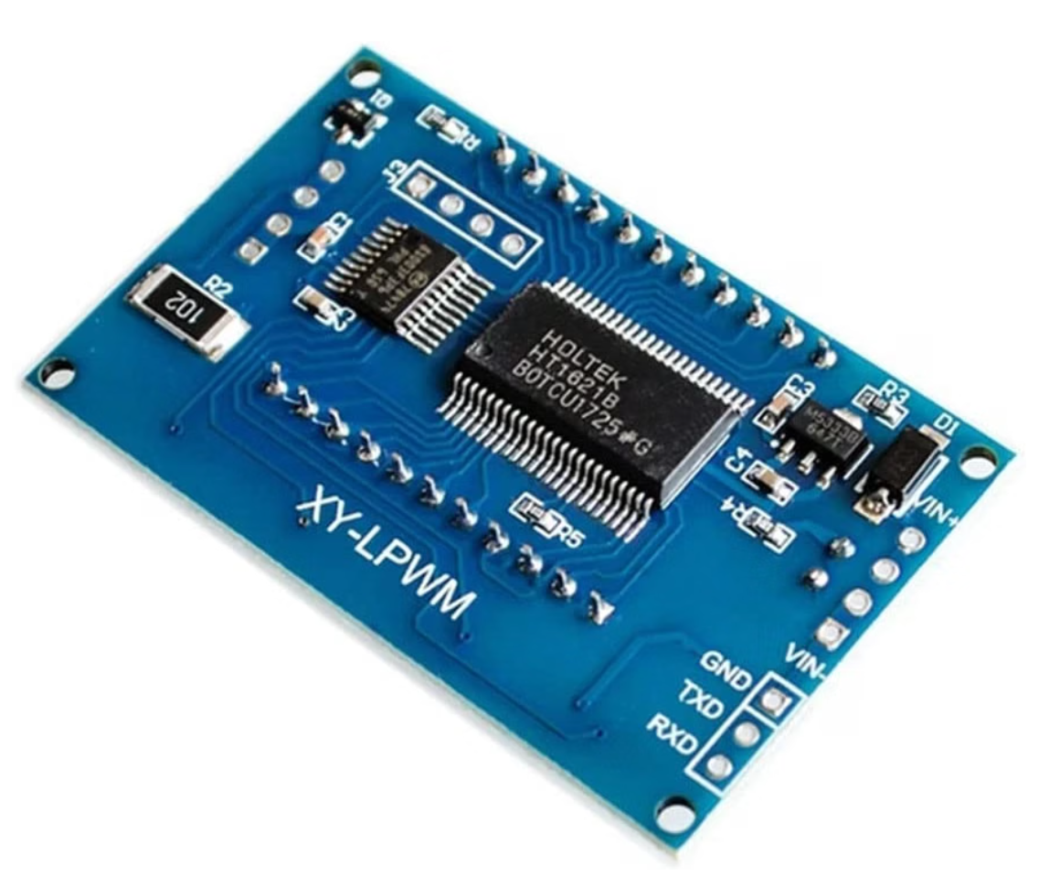
The module has a straightforward layout with a set of input pins for power and multiple output pins to connect one or more devices. The board does not come with a protective case, so it's advisable to handle it carefully to avoid damaging the components on the back. You may need to solder pin headers to the board for easy connection to a breadboard or other wiring.
Hardware Components
- XY-LPWM PWM Signal Generator Module
- 5V Power Supply (e.g., from an Arduino or a dedicated power source)
- Servo Motor (for demonstration)
- Jumper Wires
- Pin Headers (if not pre-soldered)
Wiring Guide
Wiring the XY-LPWM is a simple process. The module requires a 5V power input to operate. The output pins provide the ground, signal, and positive voltage connections for your controlled device.
For a basic servo motor hookup, you will need to make the following connections:
- Connect the 5V and GND pins on the XY-LPWM to your power source.
- Connect the Signal (often orange or yellow) wire of the servo to the PWM output pin on the module.
- Connect the GND (often brown or black) wire of the servo to the GND output pin on the module.
- Connect the Power (often red) wire of the servo to the 5V output pin on the module.
This setup allows the module to control the servo's position by varying the duty cycle of the signal, as demonstrated in the video.
Live Project Demonstration
In the video, the XY-LPWM is first connected to a servo motor. The presenter demonstrates how adjusting the duty cycle percentage on the module directly controls the servo's arm position, moving it from one extreme to the other. This shows the core functionality of the device for servo control.
The demonstration then moves to an oscilloscope to analyze the generated signal's accuracy. The presenter shows the frequency and duty cycle readings on the scope and compares them to the values displayed on the module. The test reveals that the module's output is highly accurate, especially at lower frequencies, making it a reliable tool for precise applications. The video also highlights that while the frequency can be adjusted, the proper method for controlling a servo is to maintain a fixed frequency (typically 50-100 Hz) and vary the duty cycle.
Chapters
- [00:06] Introduction to the XY-LPWM PWM Generator
- [00:31] Hardware Overview and Setup
- [01:38] Controlling a Servo Motor with Duty Cycle
- [03:51] The Effect of Frequency on Servo Control
- [04:12] Testing Signal Accuracy with an Oscilloscope
- [07:17] Final Thoughts and Product Review
画像
必要かもしれないもの
-
アマゾン
-
アリエクスプレスBuy XY-LPWM 1Hz-150KHz PWM Signal Generator Module - AliExpresss.click.aliexpress.com
リソースと参考文献
まだリソースはありません。
ファイル📁
ファイルは利用できません。