本教程是的一部分: 伺服电机
这里列出了所有与伺服电机相关的视频。其他视频的链接在本文下方。

Controlling a Servo with Push Buttons Using Arduino
In this tutorial, we will learn how to control a servo motor using two push buttons, one for moving the servo to the left and another for moving it to the right. When you press the right button, the servo will move by 10 degrees to the right, and when you press the left button, it will move by the same amount to the left. If you hold a button down, the servo will continue to move in that direction until you release it.

This project is a great way to understand how to interface buttons with a servo motor using Arduino. We will cover the necessary hardware components, wiring instructions, and the code needed to make it all work. For a clearer understanding, you can refer to the video accompanying this tutorial (in video at 01:00).
Hardware Explained
For this project, you will need an Arduino board, a servo motor, and two push buttons. The servo motor is responsible for the movement, while the push buttons act as inputs to control the direction of that movement. The Arduino processes these inputs and sends the appropriate signals to the servo.
The servo motor operates based on pulse-width modulation (PWM) signals. By sending different pulse widths, you can control the angle of the servo. The push buttons will be connected to digital input pins on the Arduino, and we will use internal pull-up resistors to simplify the wiring.
Datasheet Details
| Manufacturer | Various |
|---|---|
| Part number | SG90 |
| Logic/IO voltage | 5 V |
| Supply voltage | 4.8–6 V |
| Output current (per channel) | 1.5 A max |
| Peak current (per channel) | 2.5 A max |
| PWM frequency guidance | 50 Hz |
| Input logic thresholds | 0.3VCC to 0.7VCC |
| Voltage drop / RDS(on) / saturation | 0.4 V |
| Thermal limits | 85 °C |
| Package | Plastic |
| Notes / variants | Standard 180° rotation |
- Ensure the servo is rated for your supply voltage.
- Use appropriate heat sinking if operating at high currents.
- Connect buttons to ground with pull-up configuration.
- Debounce your buttons if experiencing erratic behavior.
- Monitor the serial output for debugging.
Wiring Instructions

To wire the components, start by connecting the servo motor. Connect the red wire of the servo to the 5V pin on the Arduino, the black wire to the GND pin, and the yellow or white signal wire to pin 9 on the Arduino. This pin will control the position of the servo.
Next, wire the push buttons. Connect one terminal of the right button to pin 2 and the other terminal to ground. For the left button, connect one terminal to pin 12 and the other terminal to ground as well. This setup allows the internal pull-up resistors to keep the pins high when the buttons are not pressed.
Code Examples & Walkthrough
Let's begin with the code for controlling the servo with a single push button. The code initializes the servo object and sets an initial angle. Here's a short excerpt:
int angle = 90;    // initial angle for servo
int angleStep = 10; // step size for movement
In this snippet, angle represents the current position of the servo, while angleStep defines how much the servo moves with each button press. This code is essential for tracking the servo's position.
Next, we have the setup function where we attach the servo and configure the input pins:
void setup() {
  Serial.begin(9600);          // setup serial
  myservo.attach(9);  // attaches the servo on pin 9
  pinMode(2, INPUT_PULLUP); // configure button pin
}
In the setup, we initialize the serial monitor and attach the servo to pin 9. The button on pin 2 is set as an input with a pull-up resistor, which simplifies wiring and avoids the need for external resistors.
Finally, we look at the loop function that handles the button press:
while(digitalRead(2) == LOW) {
  angle = angle + angleStep; // increment angle
  myservo.write(angle); // move servo
}
This loop continuously checks if the button is pressed. When it's pressed, the angle increases by the defined step, and the servo moves accordingly. It's crucial to ensure that the angle stays within bounds (0 to 180 degrees) to prevent damage to the servo.
Demonstration / What to Expect
When you press the right button, the servo should move to the right in increments of 10 degrees until it reaches the maximum of 180 degrees. Similarly, pressing the left button will move it to the left. If you hold down a button, the servo will keep moving in that direction until you release the button (in video at 01:00).
Common pitfalls include wiring issues, such as incorrect connections or floating inputs. Always ensure that your connections are secure and that you are using the correct pins as specified in the code.
图像


本教程是……的一部分: 伺服电机
- Control a Servo Motor with a Push Button: Move Servo and Return SPB-1
- Control a Servo Motor with a Push Button: Move Servo in One Direction SPB-2
- Controlling a Servo Motor with a Push Button: Move Servo While Button Is Pressed (SPB-3)
- Controlling a Servo with a Potentiometer Using Arduino
- Controlling a Servo with Potentiometer and LCD1602 using Arduino
- 使用红外遥控器和Arduino控制伺服电机
- 使用电位器控制Arduino伺服电机
- 通过手势控制Arduino的伺服位置
- Controlling Two or More Servos with Potentiometers Using an Arduino
- How to Control a 360° Servo with Three Push-Button Switches
- How to Use Continuous 360° Servo with Arduino
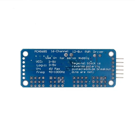
- PCA9685 16通道12位伺服控制器V1的Arduino代码和视频
- Build an Arduino Servo Toggle Switch with a Push Button
This code has not been parsed yet. Please return to the admin panel to parse it.This code has not been parsed yet. Please return to the admin panel to parse it.|||您可能需要的东西
-
亚马逊亚马逊上的伺服电机amzn.to
-
全球速卖通从AliExpress购买SG90伺服电机180或360。s.click.aliexpress.com
资源与参考
尚无可用资源。
文件📁
没有可用的文件。